1 2 3 4 5 6 7
8
9
Specifications
76
IN
finity
610
User’s Guide
8.1.5.
Digital Input/Output Specifications
Connector
Phoenix Contact PN 1881422
Input
5 to 24 Vdc, 1 to 5 mA, Optically Isolated
Output
Open Collector (3 to 40 V, 100 mA Max)
Signals
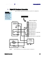
Pin 1 – Digital Common Voltage Reference for DIN1/DIN2
Pin 2 – DIN1 (Digital Input 1)
Pin 3 – DIN2 (Digital Input 2)
Pin 4 –- Digital Common Voltage Reference for DIN3/DIN4
Pin 5 – DIN3 (Digital Input 3)
Pin 6 – DIN4 (Digital Input 4)
Pin 7 – Digital Common Ground
Pin 8 – DOUT1 (Digital Output 1)
Pin 9 – DOUT2 (Digital Output 2)
Pin 10 – DOUT3 (Digital Output 3)
Pin 11 – DOUT4 (Digital Output 4)
Pin 12 – Digital Common Ground
NOTE: Pins 7 and 12 can be used for both inputs and outputs.
Pin 1 is on the left when facing the end of the reader.
8.1.6.
Ethernet LAN Specifications
Connector
RJ-45
Ethernet
10/100 BaseT
Indicators
Yellow - Indicates link is operational
Green - Indicates network traffic detected.
Signals
Pin 1 – TXD+ (Transmit Data +)
Pin 2 – TXD- (Transmit Data -)
Pin 3 – RXD+ (Receive Data +)
Pin 4 – NC
Pin 5 – NC
Pin 6 – RXD- (Receive Data -)
Pin 7 – NC
Pin 8 – NC
Содержание INfinty 610
Страница 1: ......
Страница 8: ...Contents vi INfinity 610 User s Guide This page intentionally left blank ...
Страница 75: ...1 2 3 4 5 6 7 8 9 Reader Configuration Tool INfinity 610 User s Guide 67 ...
Страница 98: ...Appendix B IN610 DIO Interface Module 90 INfinity 610 User s Guide 8 Click the Change Settings button ...
Страница 106: ...Appendix C Disposal of the INfinity 610 Reader 98 INfinity 610 User s Guide This page intentionally left blank ...
Страница 107: ...INfinity 610 User s Guide This page intentionally left blank ...
Страница 108: ...INfinity 610 User s Guide ...


