


Instruction manual
20220919D
9
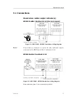
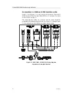
Figure 3-6 RI35 Mk2-J3XX (old), independent function of autopilot
Note !
In order to use the indicator when the autopilot is switched off, the
RI35 Mk2 Limiter must be connected as shown.
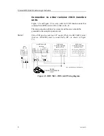
Connection to J45A/J45S Junction units
Note !
When the RF45X Rudder Feedback Unit is connected to J45A or J45S
junction units, the S1 plug-in strap on the RF45X PCB must be set to
position “AP45”.
* Non polarized (colour independant)
J45A JUNCTION UNIT
RF45X
RUDDER FEEDBACK
UNIT
12 11 10
GN
D
RU
DDE
R
F
B
I
/P
+O
U
T
BL
U
E
GRE
E
N
RE
D
*
FR E Q S U PP L Y
C UR R
RI35 Mk2
RUDDER ANGLE
INDICATOR
S UPP LY VOL TAG E 12 /24 V
RI35 Mk2
RUDDER ANGLE
INDICATOR
FR E Q S U PP L Y
C UR R
*
N ME A
N ME A
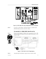
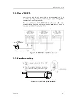
Figure 3-7 RI35 Mk2 - J45A Wiring diagram
Note !
Autopilot supply and Indicator supply must have common GND.


