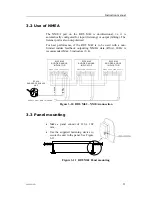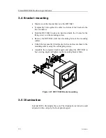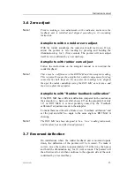
Simrad RI35 Mk2 Rudder Angle Indicator
6
20220919D
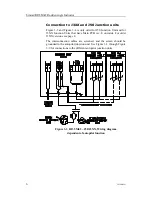
Connection to J3XX and J50 Junction units
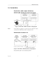
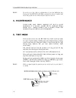
Figure 3-3 and Figure 3-4 is only valid for J50 Junction Unit and for
J3XX Junction Units that have Main PCB rev. E onwards. For older
J3XX versions see page 8.
The interconnection cables are screened, and the screen should be
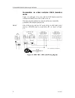
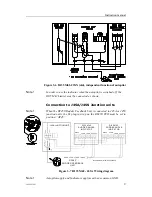
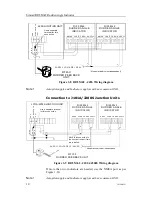
grounded in the autopilot junction unit. See Figure 3-3 through Figure
3-9 for connections to the different autopilot junction units.
Figure 3-3 RI35 Mk2 – J50/J3XX, Wiring diagram
dependent of autopilot function


