Instruction manual
20220919D
5
3.1
Connections
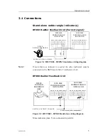
Stand alone rudder angle indicator(s)
RF45X Rudder Feedback Unit (Current signal)
F R E Q S U P P L Y
C U R R
R F45 X
R UD DE R FE ED BA CK
U NIT
RI35 Mk2
RUDDER ANGLE
INDICATOR
S UPP LY VOL T AG E 12 /2 4VD C
RI35 Mk2
RUDDER ANGLE
INDICATOR
G
R
EEN
RED
BL
U
E
+
+
+
+
F R E Q S U P P L Y
C U R R
N M E A
N M E A
Figure 3-1 RI35 Mk2 - RF45X Stand alone wiring diagram
Note !
If more than one indicator is needed, the other indicators must be
connected via the NMEA ports. Max. 5 indicators (1+4).
RF300 Rudder Feedback Unit
* Non polarized (colour independant)
F R E Q S U P P L Y
C U R R
RF300
RUDDER
FEEDBACK
UNIT
RI35 Mk2
RUDDER ANGLE
INDICATOR
RI35 Mk2
RUDDER ANGLE
INDICATOR
*
*
F R E Q S U P P L Y
C U R R
S UP P LY VO LT AG E : 12/24V D C
N M E A
N M E A
Figure 3-2 RI35 Mk2 – RF300 Stand alone wiring diagram
More indicators (max. 5) are connected in parallel.


