8.9
OVERHEAT THERMOSTAT
The overheat thermostat (1 fig. 24) is positioned in a phial
pocket alongside the air separator in the flow pipe.
– Remove the outer casing as described in section 5.1.
– From below the boiler, unscrew and remove the
overheat thermostat locking nut to release the thermo-
stat body.
– Remove the two screws TCB M4 x 10 (2 fig.14) and
pivot the control box downwards, then remove the two
self tapping screws (1 fig. 14) and remove the control
box cover.
– Withdraw the thermostat then pull off the two electrical
connections
– Remove the lower “key ring” securing the thermostat
phial in its pocket and remove the phial by sliding it
downwards. Withdraw the phial through the grommet
in the control box.
– Re-assemble in reverse order ensuring that the new
phial is coated in heat sink compound (supplied) and
correctly positioned and secured in it’s pocket. Note that
the electrical polarity is immaterial.
8.10
THERMISTOR - C.H. OR D.H.W.
The thermistors are screwed in fittings on the flow pipe
(C.H.) and D.H.W. outlet pipe (D.H.W.). The thermistors do
not penetrate the waterways, therefore it is not necessary to
drain the appliance (fig. 24).
– Remove the outer casing as described in section 5.1.
– Pull off both electrical connections from the faulty ther-
mistor, unscrew the thermistor, replace and re-assemble
in reverse order using the heat sink compound supplied.
Note that the polarity of the thermistor connections is
immaterial.
The sensors are NTC mod. ST03 ones and are inter-
changeable.
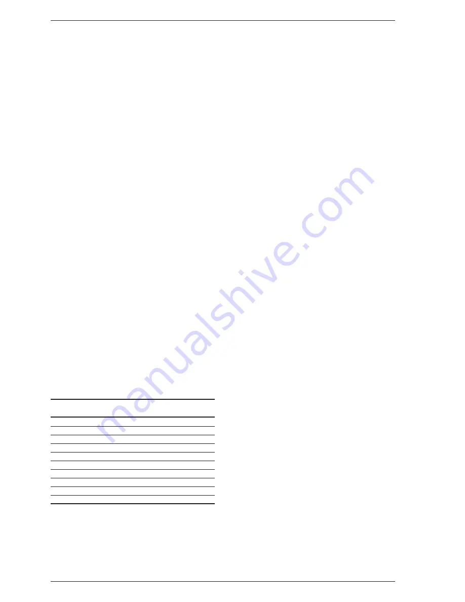
Table 9 shows the resistance values that are obtained on the
sensors as the temperature varies
8.11
IGNITION PCB
– Remove the outer casing as described in section 5.1.
– Remove the two screws TCB M4 x 10 (2 fig. 14) and
pivot the control box downwards, then remove the two
self tapping screws (1 fig. 14) and remove the control
box cover.
– Pull off the four connector blocks and the H.T. lead from
the ignition PCB. (The R.H.S. - smaller - PCB), then relea-
se the PCB from it’s mountings.
– Replace the PCB and reassemble in reverse order.
8.12
DRIVER PCB
– Remove the outer casing as described in section 5.1.
– Remove the two screws TCB M4 x 10 (2 fig. 14) and pivot
the control box downwards, then remove the two self tap-
ping screws (1 fig. 14) and remove the control box cover.
– Pull off the six connector blocks from the driver PCB
(The L.H.S. - larger - PCB).
– Pull off the potentiometer control knobs (1 - 3 fig. 17),
and unscrew the locking nuts. Release the PCB from it’s
mountings by rotating the mounting pins ⁄turn anti-
clockwise, and lift it out of the control box taking care
not to lose the potentiometer spacers.
– Replace the PCB and reassemble in reverse order. Do not
forget to re-fit the spacers.
8.13
PUMP
– Remove the outer casing as described in section 5.1.
– Isolate the C.H. flow and return valves (23 fig. 2), and
drain the appliance through the drain plug situated
below the pump.
– Swivel the pump and remove the plastic pump cover (1
screw); disconnect the electrical connections to the pump.
– Support the pump to prevent it from rotating, and
unscrew both union connections.
– Replace the pump, and reassemble in reverse order,
using the new gaskets supplied with the pump. If the
new pump is fitted with a speed adjuster, ensure that
the speed is set to maximum.
– Refill and commission the system as described in section
4.1.
8.14
D.H.W. HEAT EXCHANGER
– Remove the outer casing as described in section 5.1.
– Isolate the C.H. flow and return valves, and the D.H.W.
isolation valve (23 - 21 fig. 2).
– Drain the appliance through the drain plug situated
below the pump and the drain point at the bottom of
the D.H.W. heat exchanger.
– Drain the D.H.W. circuit by opening any D.H.W. tap
below the level of the boiler.
– Remove the two screws TCB M4 x 10 (2 fig. 14) and
pivot the control box downwards.
– Disconnect all union connections to the D.H.W. heat
exchanger and remove the heat exchanger.
– Fit new heat exchanger and reassemble in reverse order
using the new gaskets supplied with the heat exchan-
ger. Refill and re-commission the system as described in
section 4.1.
8.15
DIVERTOR VALVE - COMPLETE
– Remove the outer casing as described in section 5.1.
– Isolate the C.H. flow and return valves, and the D.H.W.
27
TABLE 9
Temperature
Resistance
C°
Ω
20
12,000
30
8,300
35
6,900
40
5,800
45
4,900
50
4,100
55
3,500
60
3,000
70
2,200
80
1,700
Содержание SUPER 102
Страница 1: ...Super Combination Boilers installation and servicing instructions...
Страница 2: ......
Страница 25: ...21 7 INTERNAL WIRING DIAGRAMS AND VIEWS 7 1 FUNCTIONAL FLOW WIRING DIAGRAM Fig 23 a...
Страница 26: ...22 7 2 ILLUSTRATED WIRING DIAGRAM Fig 23 b...
Страница 35: ......


