


S i M 3 L 1 x x
Rev 1.1
51
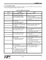
4.9. Reset Sources
Reset circuitry allows the controller to be easily placed in a predefined default condition. On entry to this reset
state, the following occur:
The core halts program execution.
Module registers are initialized to their defined reset values unless the bits reset only with a power-on
reset.
External port pins are forced to a known state.
Interrupts and timers are disabled.
AHB peripheral clocks to flash and RAM are enabled.
Clocks to all APB peripherals other than the Watchdog Timer and DMAXBAR are disabled.
All registers are reset to the predefined values noted in the register descriptions unless the bits only reset with a
power-on reset. The contents of RAM are unaffected during a reset; any previously stored data is preserved as
long as power is not lost.
The Port I/O latches are reset to 1 in open-drain mode. Weak pullups are enabled during and after the reset. For
VBAT Supply Monitor and power-on resets, the RESET pin is driven low until the device exits the reset state.
On exit from the reset state, the program counter (PC) is reset, and the system clock defaults to the internal low-
power oscillator. The Watchdog Timer is enabled with the low frequency oscillator as its clock source. Program
execution begins at location 0x00000000.
All RSTSRC0 registers may be locked against writes by setting the CLKRSTL bit in the LOCK0_PERIPHLOCK0
register to 1.
The reset sources can also optionally reset individual modules, including the low power mode charge pump,
UART0, LCD0, advanced capture counter (ACCTR0), and RTC0.
Figure
4.4.
SiM3L1xx Reset Sources Block Diagram
Содержание SiM3L1xx
Страница 2: ...2 Rev 1 1 ...
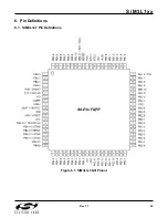
Страница 55: ...SiM3L1xx Rev 1 1 55 6 Pin Definitions 6 1 SiM3L1x7 Pin Definitions Figure 6 1 SiM3L1x7 GQ Pinout ...
Страница 62: ...SiM3L1xx 62 Rev 1 1 6 2 SiM3L1x6 Pin Definitions Figure 6 2 SiM3L1x6 GQ Pinout ...
Страница 63: ...SiM3L1xx Rev 1 1 63 Figure 6 3 SiM3L1x6 GM Pinout ...
Страница 69: ...SiM3L1xx Rev 1 1 69 6 3 SiM3L1x4 Pin Definitions Figure 6 4 SiM3L1x4 GM Pinout ...
Страница 74: ...SiM3L1xx 74 Rev 1 1 6 4 TQFP 80 Package Specifications Figure 6 5 TQFP 80 Package Drawing ...
Страница 81: ...SiM3L1xx Rev 1 1 81 6 6 TQFP 64 Package Specifications Figure 6 9 TQFP 64 Package Drawing ...
Страница 89: ...SiM3L1xx Rev 1 1 89 Figure 7 3 SiM3L1x4 GM Revision Information ...