


.
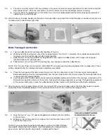
Joining The Wing Panels
15.
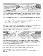
a. Trial fit the two wing halves with the dihedral brace installed between the main wing spars. Be certain that the
dihedral brace is not preventing the panels from making solid contact with each other at the center. If necessary, trim
or sand the dihedral brace for a snug fit.
b. Glue the dihedral brace into ONE of the wing panels. Make certain that it is positioned accurately between the main
wing spars.
c. Use slow CA or epoxy (either 5-minute or slow-dry) to join the two wing panels. Apply glue to the end ribs and the
exposed edges of the dihedral brace, then carefully slide the other wing panel into place. Before the glue dries, make
certain that the leading and trailing edges of each panel are aligned. The dihedral angle of 1 deg. per wing panel will
be automatically built in by the dihedral brace. If you want to check the angle, place the wing on a table so that one
wing panel sits flat, and the other is raised. The distance from the table to the bottom of the outmost wing rib should
be 1"; although a variation of up to 1/4" either way is acceptable. The most important thing is to have a solid joint at
the wing center with no gaps.
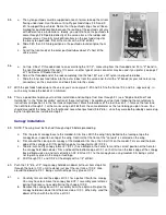
16.
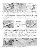
a. When dry double check through the servo opening and center sheeting opening on the bottom that the dihedral
brace is glued solidly to the main wing spars and the W-1 wing ribs.
b. Glue the die-cut Lie-Ply backplate (BP) into the aft end of the servo opening. When dry, trim BP flush with the bottom
center sheeting.
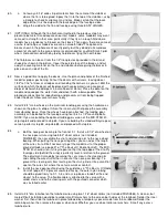
17.
a. The aileron torque rods have been pre-bent so that the threaded portion leans rearward slightly inside the fuselage
(see the W-1 wing rib cross-section on the plans). That small angle will provide your MID-STAR 40 with a bit of
differential movement (more up that down) in the ailerons, which makes for smoother rolling characteristics. Prepare
the torque rods for installation by roughening the brass bearings with sandpaper, then wiping them clean.
b. Locate the 1/4" sq. x2" basswood grooved torque rod blocks and cut a notch in each of them as shown in the photo.
c. Glue the torque rods into the blocks being very careful not to get any glue in the brass bearings. The outer end of the
bearings should be even with the outer end of the blocks.
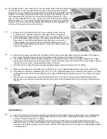
18.
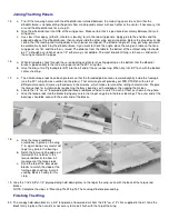
a. Glue the torque rod/block
assemblies in place on the wing
T.E., again being very careful not
to get any glue in the bearings.
b. Notch the balsa trailing edge just
forward of the notches in the
torque rod blocks to allow full
movement of the torque rods.
c. Sand the top of the basswood
blocks to match the slope of the
trailing edge sheeting. A small
sanding block is handy for this
step.
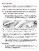
19.
Glue the 1/16"x3/4"x1-1/2" plywood wing hold-down plates to the top of the wing, even with the back of the torque rod
blocks.
NOTE: Complete the steps in "Mounting The Wing To The Fuselage" before proceeding.
Finishing The Wing
20.
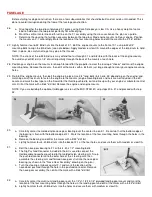
The canopy hold-down block is a 3/4" long piece of basswood cut from the 3/8" sq. x12" stick supplied in the kit. Glue the
block firmly in place, then sand it as necessary to make it flush with the top of the wing.