

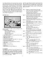


8
❑
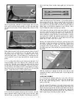
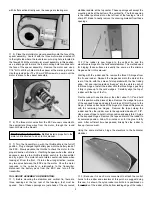
5) The main landing gear and wheels are now installed.
On the bottom of the fuselage, behind the battery hatch you will
find a slot with a holes drilled on each side. Insert the short 90
O
bent end of the one of the 4 mm dia. main landing wire forms into
one of these holes, pressing the adjacent straight part of the wire
into the slot. Repeat this process with the remaining opposite
landing gear wire. These wires should nestle down into the slot,
flush with the bottom of the fuselage.
Note that it might be
necessary to slightly adjust the short vertical ends of the wire to
get these two adjacent wires to lay correctly in the fuselage slot.
❑
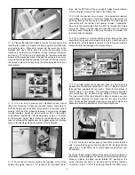
6) The two remaining nylon landing gear retainer straps are
now used to retain the adjacent landing gear wires, as shown.
Place one of the nylon retainers centered over the nested wire slot
and use a sharp pencil to mark the mounting screw locations onto
the fuselage. Use a 1/16" bit to drill two pilot holes for the screws.
Repeat this process for the opposite retainer strap. Install the
straps in place with four T2.6 x 12 mm PWA screws.
❑
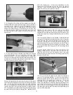
7) Slide a 4 mm nylon spacer onto each wheel axle, up to the
bend. Slide a 70 mm dia. wheel onto each axle, followed by a
wheel collar. Tighten the wheel collars, leaving just enough wheel
spacing to avoid binding. As before, we recommend filing small
"flats" into the wheel axles, directly beneath the wheel collar
setscrews.
MOTOR INSTALLATION:
As mentioned earlier in the MOTOR SELECTION section of this
manual, you will now have to have your own motor and ESC
available for the following steps.
As also mentioned earlier,
the following steps show the installation of the HIMAXX
#HC3522-0990 brushless outrunner motor. This HIMAXX motor
also comes with a motor mount system and an appropriate
propeller adaptor. If you have chosen a different motor, be aware
that you will also need a propeller adapter and that you may have
to depart from these steps to fit and mount it.
❑
1) Following the instructions that came with your HIMAXX
motor, assemble the motor to the mounting system and then,
secure the propeller adaptor to the output shaft.
❑
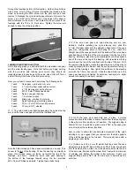
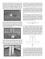
2) From the kit contents, locate the motor spacer bag
containing the six 3 mm lite-ply spacer rings and the four
T3 x 20 mm PWA mounting screws. The provided spacers are
included for the purpose of moving the motor forward from the
firewall to a distance of 3-5/8", measured from the back face of the
spinner base to the firewall, as shown.
In HIMAXX motor
installation, all six spacers were required to obtain this
measurement.
❑
3) The spacer rings are now stacked and glued together,
using epoxy glue. Note that the flat sections of each spacer must
be aligned to provide clearance spacing for the nose gear steering
arm. This is most easily accomplished by gluing the spacers to
each other while holding the flat sections to a flat work surface.
❑
4) When the glued spacer stack has cured, again use epoxy
glue to glue the spacer assembly directly to the fuselage firewall
with its center hole aligned with the center hole in the firewall and