


9
with its flat section directly over the nose gear steering arm.
❑
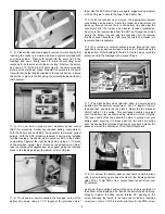
5) Place the motor/motor mount assembly onto the face of the
spacer assembly. Center it with the three motor wires oriented off
to the right side where the round laser-cut wiring hole is located in
the firewall. With the motor/motor mount assembly in this position,
use a sharp pencil to mark the four mounting hole locations onto
the face of the spacer assembly. Remove the motor and use a
1/16" bit to drill four holes into the spacer at the marks just made.
Use the provided four T3 x 20 mm PWA screws to, now, mount the
motor in place to the spacer assembly.
❑
6) The three motor wires from the ESC are now connected to
the appropriate three wires from the motor, through the round
laser-cut hole in the firewall.
❑
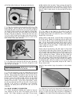
7) Turn the transmitter on, with the throttle stick in the full off
position. Plug a charged flight battery pack into the battery lead of
the ESC. Slowly advance the throttle to check the motor for the
proper direction of rotation. If nothing happens when the stick is
advanced, reverse the throttle function switch in the transmitter
and try again. The motor should rotate counter-clockwise when
looking at it from the front. If it turns the wrong direction, reverse
any two wires between the ESC and the motor. Once the motor
responds in the correctly in relationship to the transmitter,
disconnect the battery pack from the ESC and turn off the
transmitter.
TAIL GROUP ASSEMBLY AND MOUNTING:
❑
1) Before mounting the stabilizer and vertical fin, there are
three openings at the top rear of the fuselage, that must be
opened. Two of these openings are just ahead of the uncovered
stabilizer saddle, at the top center. These openings will accept the
mounting stubs at the bottom of the vertical fin. The third opening
is the rudder pushrod slot on the left rear of the fuselage. Use a
sharp #11 blade to neatly remove the covering material from these
openings.
❑
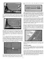
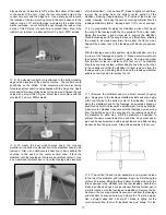
2) The rudder is now hinged to the vertical fin and the
elevators are hinged to the horizontal stabilizer. The method used
for hinging these surfaces is exactly the same as the ailerons
hinged earlier in this manual.
Starting with the rudder and fin, remove the three CA hinges from
the fin and rudder. Reinsert the hinges back into the slots at the
rear of the fin, with their die-cut slots parallel with the fins trailing
edge. Cut and insert cardstock "wedges" into the slots in each of
the three hinges. Install the rudder onto the three hinges, pushing
it fully in place up to the card wedges. Carefully align the top of
rudder with the top of the fin.
Flex the rudder in one direction or the other, about 1-1/2" and hold
it in this position with a piece of tape. Remove the wedge from one
of the exposed hinges and apply four drops of thin CA glue to the
hinge - 2 drops on each side of the hinge slot. Repeat this process
with the remaining two hinges.
Remove the tape holding the
rudder and flex the rudder over to the opposite side about 1-1/2".
Use a piece of tape to hold it in this position and apply thin CA glue
to the exposed hinges. Remove the tape and return the rudder to
its centered position. Allow 10 minutes or so for the glue to fully
wick. After sufficient time has passed, briskly flex the rudder to
free up its movement.
Using the same methods, hinge the elevators to the horizontal
stabilizer.
❑
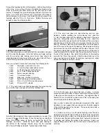
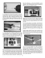
3) Because it is much more convenient to attach the control
horns to the rudder and elevators at this point, we suggest doing
this now. As shown, the nylon rudder control horn is positioned on
the left side of the rudder, at the bottom leading edge of the rudder.
IMPORTANT SAFETY NOTE: Do Not install a propeller to the
motor until instructed to do so in this manual.