


12
to shrink it firmly over the wire and wood joint. Use the second
piece of heat shrink tubing to cover and secure the opposite end
of the pushrod.
❑
3) The elevator pushrod is now made in the same way, using
the longer 23-5/8" wood pushrod dowel, with the 110 mm pushrod
wire at one end and the remaining 100 mm pushrod wire with the
RC link at the opposite end. The elevator pushrod will be installed
last, it can be set aside for now.
❑
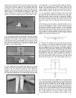
4) Remove the rudder servo output arm retaining screw and
remove the output arm from the servo. Install the brass pushrod
connector into the inside hole in the output arm and secure it in
place with the lock washer. Reinstall the output arm back onto the
servo perpendicular to the servo body with the pushrod connector
aligned with the nose gear steering tube. Once the arm is in this
position, replace the retaining screw.
❑
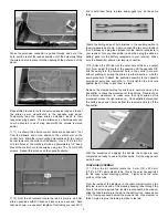
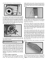
5) The rudder pushrod assembly is now installed. To feed the
rudder end of the pushrod through the pushrod exit slot at the top
rear of the fuselage, it is first necessary to remove the RC link and
lock nut from the longer rear pushrod wire. As shown, slightly
bend the pushrod wire up to access the pushrod slot from inside
the fuselage.
Insert the pushrod into the fuselage through the wing opening,
guiding it back toward the tail. Maneuver the pushrod until the
threaded pushrod end exits the slotted hole at the top rear of the
fuselage, next to the fin. Pull the wire out of the slot far enough to
straighten out the bend that was just made. Thread the lock nut all
the way onto the pushrod threads and then the RC link all the way
onto the threads, leaving about 1/16" between it and the lock nut.
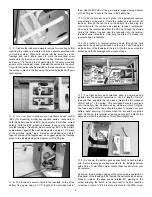
At the servo end of the pushrod, again thread the lock
nut all the way onto the threads, followed by the RC link. Install the
RC link to the outermost hole in the rudder servo output arm. Now,
lock the rudder in neutral to the vertical fin, using tape or clamps,
as shown.
Now, thread the RC link at the rudder in or out as needed to
connect it to the outermost hole in the nylon rudder horn.
❑
6) With the pushrod now connected to both the rudder and the
rudder servo, thread both lock nuts up to the rear barrel of the RC
links and tighten them firmly. As shown, we installed short lengths
- 1/4" or so - of fuel tubing over the RC links to hold them firmly in
place.
❑
7) Now that the rudder pushrod is in place and connected, the
nose gear pushrod is installed. From the kit contents, locate the
following parts:
1 each
3 mm OD x 300 mm (1/8" x 11-13/16") nylon
nose gear pushrod
2 each
M2 x 24 mm threaded studs
1 each
M2 RC Link
1 each
M2 nut
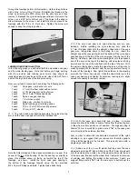
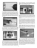
Thread one of the M2 x 24 mm studs into one end of the nylon
pushrod tube to a depth of about 3/8". As shown, this is easy to
do by using an electric drill. Chuck the stud firmly into the drill and
then simply use the power of the drill to thread the stud in place
into the nylon tube.