


5
When the extension connector is pulled through and out of the
hole, pull the rest of the lead assembly out of the hole while fitting
the aileron hatch in place into the opening at the outer end of the
panel.
Repeat this process to route the servo extension lead and to seat
the aileron servo mount/hatch in the opposite wing panel.
Temporarily tape the loose aileron extension leads to their
respective wing panels. The two aileron servo hatch/mounts can
now be secured to each wing panel with the screws removed
earlier.
❑
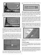
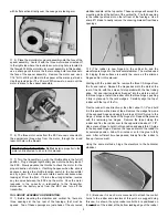
11) As shown, the aileron control horns are positioned 3" out
from the inboard end of the aileron to the vertical arm on the
control horn. Mark the two mounting hole locations for the control
horn screws onto the surface of the aileron. Use a 1/16" dia. bit to
drill two holes at the marks just made, approximately 1/2" deep.
Mount the control horn to the aileron using two T2 x 12 mm PWA
screws. Repeat this process on the opposite aileron.
❑
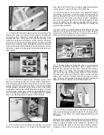
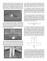
12) From the kit contents, locate the two 2.6 mm dia. x 55 mm
aileron pushrods with R/C links and lock nuts on each end. Note
that, as shown, we use short lengths of fuel tubing over each R/C
link to hold them firmly in place and suggest you do the same
thing.
Clamp the trailing edge of both ailerons in the neutral position to
the wing panels as shown. Again, connect the two servo leads to
the Y-harness and plug the harness into the aileron receptacle in
your receiver. Turn your transmitter on and then, plug the airborne
battery pack into the battery receptacle in your receiver. Make
sure the transmitter aileron trim lever is in neutral.
❑
13) Attach the R/C link into the outer hole of the servo output
arm. Now, adjust the length of the pushrod until the opposite R/C
link fits easily into the outermost hole in the control horn arm
without pushing or pulling the aileron in either direction. Use the
same procedure to attach the pushrod assembly to the opposite
wing panel servo and control horn. Firmly tighten the lock nuts
against the R/C links to lock them in place.
Remove the clamps holding the ailerons in neutral and use the
transmitter to check the movement of the ailerons. Double check
the aileron movement to make sure that right aileron stick
movement moves the right aileron up. Once satisfied, disconnect
the battery pack and Y-harness from the receiver and turn off the
transmitter.
With the exception of applying the decals, the wings are now
complete and ready to use in final assembly. Set the wing panels
aside for now.
FUSELAGE ASSEMBLY:
❑
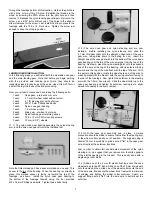
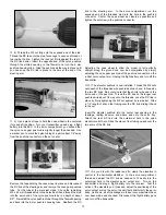
1) From the kit contents locate the 5 mm OD x 250 mm
(3/16" x 9-7/8") white plastic tube. This is the outer housing tube
for the nose wheel steering pushrod.
Lightly sand the outer
surface of the tube.
From the inside of the fuselage, in the radio compartment on the
left side, insert one end of the steering housing tube through the
hole in the small plywood tab, located just beneath side window.
Slide the tube forward into the slot in the battery tray. Leave about
1/8" of tubing exposed behind the plywood tab. Use medium or
thick CA glue to glue the tubing in place to the tab.