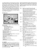
SIG Kadet Senorita EP Скачать руководство пользователя страница 2

1

KADET SENIORITA EP ARF ASSEMBLY MANUAL

INTRODUCTION:

Congratulations on your purchase of the new SIG KADET
SENIORITA EP ARF kit!  The Kadet Seniorita was originally
designed by Claude McCullough, following the same guidelines as
it's larger brother, the Kadet Senior, but in a more manageable
size. Claude put a great deal of thought into the Senior design and
came up with an R/C training aircraft, that was just about perfect.
Since it's introduction in 1987, the Kadet Seniorita became one of
the favorite trainers for thousands, with its low wing loading and
slow flight characteristics. As proof, it's safe to say that in the
following years, the Kadet Senior and Seniorita have been used to
train thousands of modelers to fly. In addition, these designs have
been used for many other applications, as well as being "kit
bashed" into any number of different configurations. The Kadet
Seniorita kit is still in production and remains a true model aviation
classic.

Over the years we have received many requests to equip the
Kadet Senior with ailerons, something we did with the ARF
version. Now, we have also added ailerons to the Kadet Seniorita
EP ARF kit, making it all that much more usable in the training role
it was designed for.

In addition, we have designed the Kadet

Seniorita EP ARF for electric power.

With the new brushless

motors and lithium polymer (LiPo) batteries, you can now enjoy
15+ minute flights, during which you can do aerobatic maneuvers
that used to only capable with typical glow engines. Electric power
allows you to climb high and shut the motor off to soar with the
birds, turn it back on again to do touch and goes before landing
and taxing back at the end of the flight. The Kadet Seniorita EP
ARF raises the benchmark for all ARF electric powered
trainer/sport airplanes. Large and slow enough to learn on at
reduced throttle settings and yet fully capable of sport aerobatics,
when called upon to do so.

The Kadet Seniorita EP ARF has been expertly covered with
transparent covering to show off its beautiful classic structure. The
wing has been designed to be a 2-piece assembly, allowing easy
transportation to and from the field and simplified storage. The
landing gear system is very forgiving, making even the worst
landings look just a bit better.

We urge you to read this assembly manual completely before
assembly. Familiarize yourself with the parts and their assembly
sequences. The successful assembly and flying of this airplane is

your responsibility. If you deviate from these instructions, you may
wind up with problems later on. The Kadet Seniorita EP ARF is
certainly a suitable R/C model for beginning modelers. However,
it is important to understand that if this is your first R/C model, you
will need to find and use a qualified R/C flight instructor to test fly
the airplane and teach you how to fly it. If this is your first radio
control mode, we urge you to NOT attempt to fly it without a
qualified instructor.

AIRCRAFT SPECIFICATIONS:
Wingspan:

63 in.

1600 mm

Wing Area:

750 sq. in.

48.4 dm

2

Length:

52 in.

1320 mm

Flying Weight:

74 oz.

2097 g

Wing Loading:

14.2 oz./sq. ft.

43.3 g/dm

2

Order Number:

SIGRC60ARF

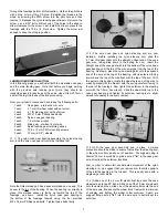
RECOMMENDED EQUIPMENT:
Motor:

400 Watt Brushless Outrunner

Battery:

3-Cell 3300 mAh Lithium Polymer

ESC:

45A (minimum)

Radio:

4 Channel with 4 Standard Servos
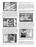
RADIO EQUIPMENT:
The Kadet Seniorita EP ARF requires a standard 4-channel radio
system with 4 standard servos. In this assembly manual, we used
and show the Hitec LASER 4 radio system with HS-322HD
standard servos.

In addition, you will need two 12" servo

extension leads and a 12" Y-harness to connect the aileron servos
to the receiver.

ELECTRIC MOTOR SELECTION:
The motor choices for your Kadet Seniorita EP ARF are many, but
in general, you will need a motor with about a 400-watt output.
For this assembly manual, we used and show the HIMAX 
HC3522-0990 brushless outrunner motor and a Phoenix 45 amp
electronic speed control (ESC). We, also, use a 3-cell, 3300 mAh
Lithium Polymer battery and a APC 10 x 7E propeller for flights in
excess of 12 minutes. With this motor the Kadet Seniorita EP ARF
will easily cruise at 1/2 throttle, yet fly most sport aerobatic
maneuvers including loops, rolls, touch and goes, and inverted
flight with less than full power. It will also fly this motor and prop
combination with a 10 cell, 3300 mAh Nickel Metal Hydride battery
pack. We strongly suggest that you choose and have available
your own motor and ESC during the assembly of this model.
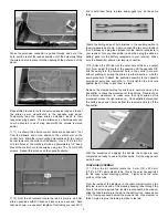
COVERING MATERIAL:
Your Kadet Seniorita EP ARF has been professionally covered with
premium covering. If you live in a drier climate, you may notice that
some wrinkles might develop after removing the covered parts from
their plastic bags.

If that is the case, there is no need to be

alarmed. The covering is not defective. This is normal and has
nothing to do with the covering material or how it was applied.

R

MODELER’S  TIP:

One of the most common problems

associated with shrinking any covering film is controlling the
heat around the seams. Heat applied too close or directly onto
seams re-heats the covering adhesive and the seams will often
"crawl". This is easy to control. Just tear a few paper towels
into strips and soak them in cool tap water. Lay the wet strips
over the covering and use a heat gun or iron as you normally
would. The wet strips keep the seam cool while the covering
immediately next to it shrinks. This tip work great with any 
iron-on covering.

Содержание Kadet Senorita EP

Страница 1: ......

Страница 2: ...e R C model for beginning modelers However it is important to understand that if this is your first R C model you will need to find and use a qualified R C flight instructor to test fly the airplane and teach you how to fly it If this is your first radio control mode we urge you to NOT attempt to fly it without a qualified instructor AIRCRAFT SPECIFICATIONS Wingspan 63 in 1600 mm Wing Area 750 sq ...

Страница 3: ... suggest removing the covered parts from their bags allowing them to adjust to the ambient humidity present in your particular geographical location Bag 1 Right Wing Covered and trimmed with a covering Aileron hinged with three 3 CA hinges not glued Aileron servo hatch mount installed with 4 ea T2 x 6 PWA Tab on front of root rib for wing hold down Trailing edge drilled for hold down bolt Receptac...

Страница 4: ...anels can be easily transported or stored requiring a minimum of space You may want to consider using a little 5 minute epoxy to permanently install the aluminum blade joiner and the rear steel locating pin into one of the panels Doing this prevents accidentally losing these parts Also if space is not an issue the two wing panels can be permanently epoxied together your call Note that as received ...

Страница 5: ...is position use a sharp pencil to mark the position of the mounting lugs Repeat this step for the opposite aileron cover hatch 8 Use epoxy or thick CA to glue two 20 mm x 20 mm x 10 mm hardwood servo mounting blocks to each aileron cover as shown When the glue has set the servos can be mounted to the hatch mounts using the servo mounting screws that came with your radio system Use a 1 16 dia bit t...

Страница 6: ...mitter on and then plug the airborne battery pack into the battery receptacle in your receiver Make sure the transmitter aileron trim lever is in neutral 13 Attach the R C link into the outer hole of the servo output arm Now adjust the length of the pushrod until the opposite R C link fits easily into the outermost hole in the control horn arm without pushing or pulling the aileron in either direc...

Страница 7: ...der and elevator servo leads up through the oval hole in the battery tray and plug the connectors into the rudder and elevator receiver receptacles Now route the receiver lead from the ESC up through the slotted hole in the battery tray and plug the connector into the receiver throttle channel receptacle Last plug the aileron Y harness into receiver aileron receptacle 6 We routed our receiver ante...

Страница 8: ...illips head bolts Tighten these bolts firmly 2 The wire nose gear and nylon steering arm are now installed Before installing the nylon steering arm slide the 4 1 mm ID wheel collar onto the straight unbent end of the nose gear wire letting slide down to the spring for now Insert the straight end of the nose gear wire into the bottom of the nylon nose gear bearing until the top of the wire emerges ...

Страница 9: ...s mentioned earlier in the MOTOR SELECTION section of this manual you will now have to have your own motor and ESC available for the following steps As also mentioned earlier the following steps show the installation of the HIMAXX HC3522 0990 brushless outrunner motor This HIMAXX motor also comes with a motor mount system and an appropriate propeller adaptor If you have chosen a different motor be...

Страница 10: ...f the vertical fin The third opening is the rudder pushrod slot on the left rear of the fuselage Use a sharp 11 blade to neatly remove the covering material from these openings 2 The rudder is now hinged to the vertical fin and the elevators are hinged to the horizontal stabilizer The method used for hinging these surfaces is exactly the same as the ailerons hinged earlier in this manual Starting ...

Страница 11: ...he wing in place on a flat surface allowing the model to be viewed accurately from either the front or rear Support the bottom rear of the fuselage with blocks magazines etc With the fuselage now in this position place the stabilizer onto the top rear of the fuselage and center it Place a small weight onto the center of the stabilizer to hold it in place Now view the model from the front or rear a...

Страница 12: ...23 5 8 8 mm dia x 600 mm Elevator pushrod dowel 1 each 5 16 dia x 17 8 mm dia x 432 mm Rudder pushrod dowel 1 each 2 6 mm x 200 mm rod threaded M2 on one end with an M2 nut and RC link and a 90O bend at the opposite end 1 each 2 6 mm x 110 mm rod threaded M2 on one end with an M2 nut and RC link and a 90O bend at the opposite end 2 each 2 6 mm x 100 mm rods threaded M2 on one end with an M2 nut an...

Страница 13: ...shrod end exits the slotted hole at the top rear of the fuselage next to the fin Pull the wire out of the slot far enough to straighten out the bend that was just made Thread the lock nut all the way onto the pushrod threads and then the RC link all the way onto the threads leaving about 1 16 between it and the lock nut At the servo end of the pushrod again thread the lock nut all the way onto the...

Страница 14: ...ighten the setscrew in the pushrod connector Adjusting the nose wheel to allow the model to roll perfectly straight along the ground can now be accomplished by simply adjusting the nose gear pushrod at the pushrod connector on the rudder servo output arm Unplug the flight battery and turn off the transmitter 10 The elevator pushrod is now installed Thread the M2 nuts onto each of the threaded wire...

Страница 15: ...from the fuselage Harden the four cowl mounting holes in the fuselage with a single small drop of thin CA glue in each hole Remount the cowl to the fuselage with the four mounting screws 4 The propeller and spinner can now be final mounted to the motor propeller adaptor Note that when trying to tighten the propeller nut the spinner backplate may slip against propeller shaft adaptor on the motor al...

Страница 16: ... that a control surface moves when you move the transmitter stick to full deflection is called the control throw or control travel This determines how responsive the airplane will be to your control inputs We suggest the following control movements for beginning R C pilots Ailerons 3 4 19 mm up 3 4 down Elevator 5 8 16 mm up 5 8 down Rudder 1 25 mm left 1 right Note These measurements are always t...

Страница 17: ...rectly before you try to fly it These first flights are called trim flights During these flights the flight instructor will trim the model from the transmitter to ensure that it flies straight and level without any problems When a brand new R C model takes off for the first time there is no way of knowing which way it might want to go Some models will try to climb while others might want to go dow...

Страница 18: ...egin making any required trim corrections with the transmitter The goal is to trim the airplane for hands off level flight at cruising speed Note that like most trainer type aircraft using a flat bottom airfoil section the Seniorita EP ARF will tend to climb under full power This is perfectly normal and is what makes the airplane want to return to stable flight if upset Many full scale pilots use ...

Страница 19: ...l size or full size are not toys Because of the speeds that airplanes must achieve in order to fly they are capable of causing serious bodily harm and property damage if they crash IT IS YOUR RESPONSIBILITY AND YOURS ALONE to assemble this model airplane correctly according to the plans and instructions to ground test the finished model before each flight to make sure it is completely airworthy an...

Страница 20: ......

Отзывы: