


2
Any wrinkles that appear in the covering are easy to remove by
using a hobby-type of heat iron. We suggest covering the iron's
shoe with a thin cotton cloth, such as an old T-shirt to prevent
scratching the film. To shrink this covering, set the temperature of
your covering iron to 220
O
F - 250
O
F (104
O
C - 121
O
C). Start by
using the heated iron to go over all the seams and color joints,
making sure they are firmly sealed and well adhered. Then, use
the heated iron to lightly shrink the material - do not press on it.
Once the covering is tight, lightly iron the covering back down to
the wood. You can use a hobby type heat gun to re-shrink the
covering, but you must be very careful to avoid heating the seams.
Your Kadet Seniorita EP ARF has been covered with a transparent
red and a black covering material.
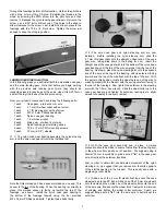
REQUIRED TOOLS:
For proper assembly, we suggest you have the following tools and
materials available.
•
A selection of glues, such as:
SIG Thin, Medium, and Thick CA
SIG Fine Tip Applicator Tips for CA
SIG CA Debonder
SIG Kwik-Set 5-Minute Epoxy
SIG Epoxy (slow cure)
•
Thread locking compound, such as Loctite
®
Non-Permanent Blue
•
Screwdriver Assortment
•
Needle Nose & Flat Nose Pliers
•
Diagonal Wire Cutters
•
Small Allen Wrench Assortment
•
Electric Drill and Assorted Small Diameter Bits -
1/32", 1/16" dia. typical
•
Pen Vise for Small Drill Bits
•
Hobby Knife with Sharp #11 Blades
•
Soldering Iron & Flux (for battery and ESC connectors)
•
Paper Towels
•
Rubbing Alcohol for Clean Up
•
Scissors
•
Covering Iron and Trim Seal Tool
•
Masking Tape
•
Sharp Pencil and a Fine-Tip Felt Marker Pen
KIT CONTENTS:
The following is a complete list of every part included with your
Kadet Seniorita ARF kit. Use the check-off blocks (
❑
) to inventory
your kit before beginning assembly. Note that the CA type hinges
for the ailerons, rudder, and elevators are in place in each of these
parts but are not yet glued in place. Also, note that the bolts and
nuts required to mount your motor are not included in this kit and
must be purchased separately.
Note that we suggest keeping the hardware parts for this kit in their
bags, as received. This is of help to you when looking for the
various parts required for the following steps. We, also, suggest
removing the covered parts from their bags, allowing them to
adjust to the ambient humidity present in your particular
geographical location.
Bag #1
❑
Right Wing - Covered and trimmed with a covering
Aileron hinged with three (3) CA hinges, not glued
Aileron servo hatch/mount installed with 4 ea. T2 x 6 PWA
Tab on front of root rib for wing hold down
Trailing edge drilled for hold down bolt
Receptacle for wing joiner blade built into main spar
3 mm dia. locator pin in root rib at rear spar location
Bag #2
❑
Left Wing - Covered and trimmed with a covering
Aileron hinged with three (3) CA hinges, not glued
Aileron servo hatch/mount installed with 4 ea. T2 x 6 PWA
Tab on front of root rib for wing hold down
Trailing edge drilled for hold down bolt
Receptacle for wing joiner blade built into main spar
Bag #3
❑
Vertical Fin and Rudder Assembly - Covered and trimmed
with a covering
Rudder hinged with three (3) CA hinges - not glued.
Bag #4
❑
Horizontal Stabilizer & Elevator Assembly - Covered and
trimmed with a covering
Stabilizer and elevator hinged with five (5) CA hinges - not
glued
Bag #5
❑
Fuselage - Covered & Trimmed with a covering
Side windows installed.
Removable bottom hatch taped in place.
Battery compartment floor and baffle installed
Servo tray in place
Four (4) M3 blind nuts in place for nose gear bearing.
Two (2) 10-32 blind nuts installed for wing hold down.
Bag #6
❑
Formed plastic cowl, trimmed, with four (4) pre-drilled
mounting holes
❑
Sub bag
4 each T2.6 x 8 mm PWA mounting screws
Bag #7
❑
Formed and trimmed windshield with 6 holes drilled for
screws
❑
Sub bag
6 each T2 x 8 PWA screws
Bag #8
❑
Landing Gear
2 each
Main Landing Gear Wire forms - 4 mm wire
1 each
Nose Gear Wire form - 4 mm wire
❑
Sub bag A
4 each 4.1 mm ID wheel collars with set screws
3 each 4 mm ID plastic spacers
3 each Landing gear & battery hatch retainer straps
5 each T2.6 x 12 mm PWA mounting screws
❑
Sub bag B
1 each 4.1 ID steering arm with set screw
4 each M3 x 15 mm Phillips head bolts
1 each Nylon nose gear bearing
1 each Hex wrench for nose gear steering arm - 1.5 mm
Bag #9
❑
Pushrod Bag
1 each 10 mm x 400 mm heat shrink tube
1 set
25 mm x 360 mm Velcro
®
fastener strip
1 each 8 mm dia. x 600 mm elevator pushrod - hardwood
dowel, drilled and grooved each end
1 each 8 mm dia. x 432 mm rudder pushrod - hardwood
dowel, drilled and grooved each end
1 each 300 mm tie wrap
1 each 5 mm O.D. x 250 mm female nose gear steering
tube