Mobility, Intelligent Traffic Systems
Sopers Lane, Poole, Dorset, BH17 7ER
Security
classification Unrestricted
Page
79 of 92
Version
3
Status
Issued
Last Editor
Alan Doyle
Date
05-Oct-2017
Document Name
Stratos Outstation General and ICM Handbook Document No. 667/HB/52250/000
Copyright © Siemens plc 2014. All Rights Reserved. Mobility and Logistics is a division of Siemens Plc
F1 – 24V I/O Fuse or
F2 – Battery Fuse
1. In addition to the Mains Supply, unplug the following cables as they may be connected
to powered external equipment:
a. LV/ELV Lamp supply.
b. I/O cable from the PSU board.
2. Remove the battery as described in section 7.3.4.
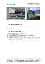
3. Remove the AC/DC power supply retaining screws from the base of the unit and rotate
the power supply module to reveal the fuses If F2 needs to be replaced the IEC inlet
connector will have to be removed. Disconnect the ¼” spade crimps from the back of
the inlet and depress the retaining tabs [two on the top and one on the bottom) to
release the connector – Refer to Figure 25.
4. The relevant fuse can now be replaced – refer to Figure 23.
5. Re-assemble unit.
Figure 24 – Power Supply Module Fixings

