Mobility, Intelligent Traffic Systems
Sopers Lane, Poole, Dorset, BH17 7ER
Security
classification Unrestricted
Page
26 of 92
Version
3
Status
Issued
Last Editor
Alan Doyle
Date
05-Oct-2017
Document Name
Stratos Outstation General and ICM Handbook Document No. 667/HB/52250/000
Copyright © Siemens plc 2014. All Rights Reserved. Mobility and Logistics is a division of Siemens Plc
4 S
YSTEM
C
OMPONENTS
4.1
System Block Diagram
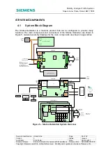
The Stratos Outstation is a modular product that can be configured to provide many
functions. The main components and connections of the Stratos Outstation are shown in
Figure 5. General assembly drawings for the main components are shown in appendices.
AC
Mains
Input
3W
10W
15W
B
a
tt
.
F
u
s
e
2
4
V
I/
O
F
u
s
e
CPU
2x GSPI RJ45
2W
24V I/O Fuse
CPU
Dual
50W
IDC
address
switch
GSPI
RS422
RJ45
IN
OUT
GSPI
RS422
RJ45
M
o
d
e
m
P
w
r
2x
GSPI
RS422
RJ45
2x
Ethernet
RJ45
2x
USB
Host
USB
Slave
2x
USB
Host
CPU
Heart
(SD Card)
License
Reset
Top
Ethernet
Bot
1
6
W
1
0
W
IEC Inlet
Internal Backup Battery
To GSPI IN on
next I/O Card
Top
Bottom
I/O Card 1
I/O Card 2
I/O Card 3
CPU Card
PSU Card
8 Inputs
+
2 Outputs
(TR2523)
Battery
Isolation
Switch
110/240V
AC Mains
Input
AC / DC Power Supply
110/240V
AC Mains
Input
24V DC
Output
Comms
Device
Stratos
UTC Instation
C
o
m
m
u
n
ic
a
tio
n
s
O
p
tio
n
s
Local User interface – Front Panel
PC
(Web/Handset)
WiFi Dongle
(Temporary
connection)
Tablet / Phone
USB to 25 way
adaptor
Legacy Handset
Terminal
RS232 +5V
LV & ELV Lamp
Supply Monitor Input
RTC Out
24V internal supply output
External 24V supply input
Force Charger Off
DC holdup capacitor input
External backup battery input
48 Inputs
+
16 Outputs
(Per card)
System
Comms
Fault
System
Comms
Busy
System
Comms
Fault
TR2523
RS232
Interface
I/O Card (3 Max)
Modem
Power
Optional TC12
Adaptor card
Figure 5 – Stratos Outstation System Overview


