


Mobility, Intelligent Traffic Systems
Sopers Lane, Poole, Dorset, BH17 7ER
Security
classification Unrestricted
Page
65 of 92
Version
3
Status
Issued
Last Editor
Alan Doyle
Date
05-Oct-2017
Document Name
Stratos Outstation General and ICM Handbook Document No. 667/HB/52250/000
Copyright © Siemens plc 2014. All Rights Reserved. Mobility and Logistics is a division of Siemens Plc
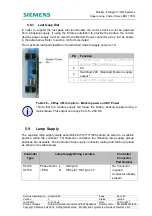
5.8.3 Last Gasp Dial
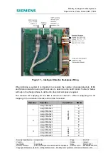
In order to support the last gasp dial functionality the comms device must be powered
from a backup supply. If using the Stratos outstation to provide the backup the comms
devices power supply must be wired to the Modem Power connector pins 2 & 3 as shown
in the table below. Refer to section 3.6 for more detail.
The maximum load permissible on the switched modem supply output is 1A.
Pin
Function
1
+24V DC input – Power for CPU board
when no PSU board is used
2
0V
3
Switched 24V (Nominal) Modem supply
output *
4
Optional RTC supply input
Table 26 – 4 Way 3.81mm pitch – Modem power and DC Power
* Note that the modem supply will follow the battery backup supply during a
mains failure. This output can range from 8 – 28V DC.
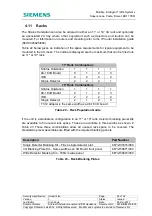
5.9 Lamp
Supply
The supplied lamp supply cable assembly 667/1/47177/000 should be wired to a suitable
position within the controller. For Siemens controllers the following lamp supply pickup
positions are available. The Controller lamp supply connector mating half will be required
as shown in the table below.
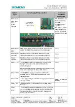
Controller
Type
Lamp Supply Wiring Location
Controller
Connector
Part Number
ST700
ST750
Phase Driver: L SK2 pin 6
/ PSU
N SK2 pin 7,SK1 pins 1-7
No Connector
required
Connector already
present