background image

i

i

NOTE

indicates information on the device, handling of the device, or the respective part of the instruction manual
which is important to be noted.

Typographic and Symbol Conventions

The following text formats are used when literal information from the device or to the device appear in the
text flow:

Parameter Names

Designators of configuration or function parameters which may appear word-for-word in the display of the
device or on the screen of a personal computer (with operation software DIGSI), are marked in bold letters in
monospace type style. The same applies to titles of menus.

1234A

Parameter addresses have the same character style as parameter names. Parameter addresses contain the
suffix 

A

 in the overview tables if the parameter can only be set in DIGSI via the option Display additional

settings.

Parameter Options

Possible settings of text parameters, which may appear word-for-word in the display of the device or on the
screen of a personal computer (with operation software DIGSI), are additionally written in italics. The same
applies to the options of the menus.

Indications

Designators for information, which may be output by the relay or required from other devices or from the
switch gear, are marked in a monospace type style in quotation marks.
Deviations may be permitted in drawings and tables when the type of designator can be obviously derived
from the illustration.
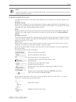
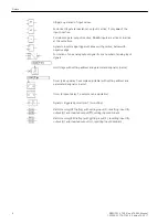
The following symbols are used in drawings:

Device-internal logical input signal

Device-internal logical output signal

Internal input signal of an analog quantity

External binary input signal with number (binary input,
input indication)
External binary output signal with number
(example of a value indication)
External binary output signal with number (device indication) used as
input signal

Example of a parameter switch designated FUNCTION with address
1234 and the possible settings 

Ein

 and 

Aus

Besides these, graphical symbols are used in accordance with IEC 60617-12 and IEC 60617-13 or similar.
Some of the most frequently used are listed below:

Analog input variable

AND-gate operation of input values

Preface

SIPROTEC 4, 7VE61 and 7VE63, Manual

5

C53000-G1176-C163-3, Edition 10.2017

Содержание SIPROTEC 4 7VE61

Страница 1: ...en Source Software Table of Contents Introduction 1 Functions 2 Mounting and Commissioning 3 Technical Data 4 Ordering Information and Accessories A Terminal Assignments B Connection Examples C Default Settings and Protocol dependent Functions D Functions Settings Information E Literature Glossary Index ...

Страница 2: ...ess relations nor does it change these All obligations of Siemens AG are stated in the relevant contractual agree ments Siemens AG reserves the right to revise this document from time to time Document version C53000 G1176 C163 3 01 Edition 10 2017 Version of the product described V4 6 Copyright Copyright Siemens AG 2017 All rights reserved The disclosure duplication distribution and editing of thi...

Страница 3: ...and power plants Applicability of this Manual This manual applies to SIPROTEC 4 Multifunction Paralleling Devices 7VE61 and 7VE63 Firmware Version V4 6 Indication of Conformity This product complies with the directive of the Council of the European Communities on the approximation of the laws of the Member States relating to electromagnetic compatibility EMC Council Directive 2004 108 EC and conce...

Страница 4: ...ollowed for personal safety as well as to avoid material damage Information is highlighted and illustrated as follows according to the degree of danger DANGER GEFAHR bedeutet dass Tod oder schwere Verletzungen eintreten werden wenn die angegebenen Maßnahmen nicht getroffen werden Beachten Sie alle Hinweise um Tod oder schwere Verletzungen zu vermeiden Danger indicates that death severe personal in...

Страница 5: ...ftware DIGSI are additionally written in italics The same applies to the options of the menus Indications Designators for information which may be output by the relay or required from other devices or from the switch gear are marked in a monospace type style in quotation marks Deviations may be permitted in drawings and tables when the type of designator can be obviously derived from the illustrat...

Страница 6: ...Limit stage with setting address and parameter designator name Timer pickup delay T example adjustable with setting address and parameter designator name Timer dropout delay T example non adjustable Dynamic triggered pulse timer T monoflop Static memory SR flipflop with setting input S resetting input R output Q and inverted output Q setting input dominant Static memory RS flipflop with setting in...

Страница 7: ...ource Software is licensed royalty free Insofar as the applicable Open Source Software License Conditions provide for it you can order the source code of the Open Source Software from your Siemens sales contact against payment of the shipping and handling charges for a period of at least 3 years since purchase of the Product We are liable for the Product including the Open Source Software containe...

Страница 8: ...8 SIPROTEC 4 7VE61 and 7VE63 Manual C53000 G1176 C163 3 Edition 10 2017 ...

Страница 9: ...Settings 32 2 1 4 3 Information List 32 2 1 5 Change Group 33 2 1 5 1 Setting Notes 33 2 1 5 2 Settings 33 2 1 5 3 Information List 33 2 2 Paralleling Functions 35 2 2 1 Functional Description 35 2 2 1 1 Connection and definitions 35 2 2 1 2 Synchronization via Transformers 37 2 2 1 3 11 2 and 2 channel Version 38 2 2 1 4 Monitoring Procedure 40 2 2 1 5 Multiple Synchronizing Points 42 2 2 1 6 Ope...

Страница 10: ...on List 86 2 6 Frequency Protection 88 2 6 1 Functional Description 88 2 6 2 Setting Notes 89 2 6 3 Settings 90 2 6 4 Information List 91 2 7 Rate of frequency change protection 92 2 7 1 Functional Description 92 2 7 2 Setting Notes 93 2 7 3 Settings 95 2 7 4 Information List 96 2 8 Jump of Voltage Vector 97 2 8 1 Functional Description 97 2 8 2 Setting Notes 99 2 8 3 Settings 100 2 8 4 Informatio...

Страница 11: ... 2 14 3 1 Information List 124 2 14 4 Min Max Measurement Setup 124 2 14 4 1 Functional Description 124 2 14 4 2 Information List 124 2 14 5 Limit Measured Values 125 2 14 5 1 Setting Notes 125 2 14 6 Statistics 125 2 14 6 1 Functional Description 125 2 14 6 2 Setting Notes 126 2 14 6 3 Information List 126 2 14 7 Set Points Statistic 126 2 14 7 1 Functional Description 126 2 14 7 2 Setting Notes ...

Страница 12: ... 170 3 3 2 Checking System Interfaces 170 3 3 3 Checking the Binary Inputs and Outputs 171 3 3 4 Checking the Analog Output 174 3 3 5 Checking the User Defined Functions 174 3 3 6 Trip Close Tests for the Configured Operating Devices 175 3 3 7 Commissioning Check 175 3 3 8 Checking the Control and Measured Voltages Circuits 175 3 3 9 Measuring the Operating Time of the Circuit Breaker 182 3 3 10 T...

Страница 13: ...ring Information and Accessories 223 A 1 Ordering Information 7VE61 224 A 2 Ordering Information 7VE63 226 A 3 Zubehör 228 B Terminal Assignments 231 B 1 Housing for Panel Flush and Cubicle Mounting 232 B 2 Housing for Panel Surface Mounting 234 B 3 Assignment of the D subminiature Connectors 236 C Connection Examples 237 C 1 7VE61 complete connection examples 238 C 2 Voltage Connectors 240 C 3 Tr...

Страница 14: ...E 3 Information List 284 E 4 Group Alarms 308 E 5 Measured Values 309 Literature 315 Glossary 317 Index 327 Table of Contents 14 SIPROTEC 4 7VE61 and 7VE63 Manual C53000 G1176 C163 3 Edition 10 2017 ...

Страница 15: ...7VE61 and 7VE63 It provides an overview of the scopes of applica tion features and of the functional scope 1 1 Overall Operation 16 1 2 Application Scope 18 1 3 Characteristics 21 1 SIPROTEC 4 7VE61 and 7VE63 Manual 15 C53000 G1176 C163 3 Edition 10 2017 ...

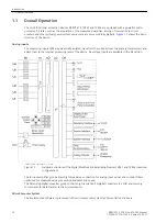
Страница 16: ...e inputs are available in the MI section hardwarestruktur ve6 200303 kn 1 en_GB Figure 1 1 Hardware structure of the digital Multifunction Paralleling Devices 7VE61 and 7VE63 maximal configuration The IA input amplifier group allows high impedance connection for analog input values and contains filters optimized for measured value processing bandwidth and speed The AD analog digital converter grou...

Страница 17: ...om the device such as configuration and setting parameters operational indications and fault messages see also 1 SIPROTEC 4 System Manual and to change setting parameters Serial Interfaces A personal computer running the DIGSI software can be connected to the serialoperator interface PC port on the front panel to conveniently operate all device functions A separate service interface can be provide...

Страница 18: ...ay and local control Synchronization Functions The devices recognize automatically the operating conditions and react depending on the pre settings In the operation mode Synchrocheck will be checked the validity of a restart according to different considerations In the operation mode Switching Synchronous Systems will be determined the frequency difference with high accuracy The connection will ta...

Страница 19: ...ant events and state changes are stored in a fault annunciation buffer The instantaneous or rms measured values during the fault are also stored in the device and are subsequently available for fault analysis Communication Serial interfaces are available for the communication with operating control and memory systems Front Interface A 9 pin DSUB socket on the front panel is used for local communic...

Страница 20: ...d values Modbus ASCII RTU This protocol of automation technology allows transmission of indications and measured values DNP 3 0 This protocol of automation technology allows transmission of indications and measured values It is also possible to provide an analog output 2 x 20 mA for output of measured values Introduction 1 2 Application Scope 20 SIPROTEC 4 7VE61 and 7VE63 Manual C53000 G1176 C163 ...

Страница 21: ...re counted Commissioning aids such as connection check field rotation check status display of all binary inputs and outputs and test measurement recording Synchrocheck Dead Line Bus Settable minimum and maximum voltage Verification of the synchronous conditions or the de energized state is also possible before the manual closing of the circuit breaker with separate limit values Fast measuring of v...

Страница 22: ...be used for network disconnection Analog Outputs Output of up to four analog operational measured values depending on the variant ordered Threshold Value Monitoring 6 freely assignable messages for threshold monitoring Implementation of fast monitoring tasks via CFC User defined Functions Internal and external signals can be logically combined to establish user defined logic functions All common l...

Страница 23: ...d software Monitoring of the input voltage circuit through double connection and opposite control Checking of the phase sequence Permanent monitoring of both closing relays BO1 and BO2 Opposite monitoring of the parallel starting algorithms Introduction 1 3 Characteristics SIPROTEC 4 7VE61 and 7VE63 Manual 23 C53000 G1176 C163 3 Edition 10 2017 ...

Страница 24: ...24 SIPROTEC 4 7VE61 and 7VE63 Manual C53000 G1176 C163 3 Edition 10 2017 ...

Страница 25: ...d functions should be used 2 1 General 26 2 2 Paralleling Functions 35 2 3 Protection and Automation Functions 81 2 4 Undervoltage Protection 82 2 5 Overvoltage Protection 85 2 6 Frequency Protection 88 2 7 Rate of frequency change protection 92 2 8 Jump of Voltage Vector 97 2 9 Threshold supervision 101 2 10 External Trip Functions 104 2 11 AnalogOutputs 106 2 12 Supervision 112 2 13 Function Con...

Страница 26: ... up on a fault but a trip signal has not been issued yet by the 7VE61 and 7VE63 because the fault was cleared by another device for example outside the own protection range These messages are then limited to faults in the line to be protected Setting Notes Spontaneous Fault Display After a fault has occurred the device display spontaneously shows the most important fault data In address 610 FltDis...

Страница 27: ... the default display which is displayed by default after startup of the device can be selected via parameter 640 Start image DD The available representation types for the measured value are listed in the Appendix Settings Addr Parameter Setting Options Default Setting Comments 610 FltDisp LED LCD Target on PU Target on TRIP Target on PU Fault Display on LED LCD 615 T MIN LED HOLD 0 60 min 5 min Mi...

Страница 28: ...OUT Power System fault 302 Fault Event OUT Fault Event 320 Warn Mem Data OUT Warn Limit of Memory Data exceeded 321 Warn Mem Para OUT Warn Limit of Memory Parameter exceeded 322 Warn Mem Oper OUT Warn Limit of Memory Operation exceeded 323 Warn Mem New OUT Warn Limit of Memory New exceeded 545 PU Time VI Time from Pickup to drop out 546 TRIP Time VI Time from Pickup to TRIP EN100 Modul 1 Functiona...

Страница 29: ... configuration Functional Description Setting of the Functional Scope Configuration settings can be entered using a PC and the software program DIGSI and transferred via the front operator interface or the rear service interface The procedure is described in detail in the 1 SIPROTEC 4 System Manual Entry of password No 7 for parameter set is required to modify configuration settings Without the pa...

Страница 30: ... of data command issuing is done 11 2 channel with the 7VE61 or 2 channel with the 7VE63 i i NOTE A mixed parametrization of three phase synchrocheck and 11 2 or 2 channel synchronising function is possible due to the identical connection If a function is not needed Disabled is set A synchronizing function group thus rendered ineffective is excluded in the menu item Synchronization all other group...

Страница 31: ...han Synchr Disabled SYNC Function group 6 167 SYNC function 7 Disabled 3ph Sync check 2chan Synchr Disabled SYNC Function group 7 168 SYNC function 8 Disabled 3ph Sync check 2chan Synchr Disabled SYNC Function group 8 173 ANALOGOUTPUT B1 Disabled Enabled Disabled Analog Output B1 Port B 174 ANALOGOUTPUT B2 Disabled Enabled Disabled Analog Output B2 Port B 175 ANALOGOUTPUT D1 Disabled Enabled Disab...

Страница 32: ...his duration is valid for all protection functions which can issue a trip command Settings Addr Parameter Setting Options Default Setting Comments 270 Rated Frequency 50 Hz 60 Hz 16 7 Hz 50 Hz Rated Frequency 280 TMin TRIP CMD 0 01 32 00 sec 0 15 sec Minimum TRIP Command Duration Information List No Information Type of Informa tion Comments 361 FAIL Feeder VT SP Failure Feeder VT MCB tripped 501 R...

Страница 33: ...g groups are not required group A is the default selection Then the rest of this section is not applicable If the changeover option is desired group changeover must be set to Grp Chge OPTION Enabled address 103 when the function extent is configured For the setting of the function parameters each of the required setting groups A to D a maximum of 4 must be configured in sequence The SIPROTEC 4 Sys...

Страница 34: ...No Information Type of Informa tion Comments 8 Set Group Bit1 SP Setting Group Select Bit 1 Functions 2 1 General 34 SIPROTEC 4 7VE61 and 7VE63 Manual C53000 G1176 C163 3 Edition 10 2017 ...

Страница 35: ...the synchronization function The voltage inputs Ua and Ub can be connected on the side 1 and the voltage inputs Ud and Ue on the side 2 Since the winding sense of the voltage inputs Ub and Ue is changed opposite the other inputs the connection of the corresponding second voltage input Ub or Ue takes place in inverse polarity also anti parallel The sum of these voltages rotated by 180 to each other...

Страница 36: ...s results for voltage U1 the frequency f1 and the phase angle α1 For the side to be synchronised index 2 is defined The electrical values of side 2 are then the voltage U2 the frequency f2 and the phases angle α2 Formation of the difference values requires definition of the absolute measurement error Δx measure value true value The reference value and thus the true value is side 1 This results in ...

Страница 37: ...values were used For unequivocal characterisation of the setting parameters the above mentioned value description was modified somewhat Inequalities were used The representation is explained using a difference voltage example To allow asymmetrical settings two setting thresholds are required A positive value for dU produces the condition U2 U1 The parameter for the setting e g for asynchronous pow...

Страница 38: ...additional angle rotation in the voltage cannot be corrected Here synchronism should always be done with the rated position of the tap changer no angle rotation Unrestricted synchronisation is always possible if voltage transformers are located on both sides of the circuit breaker 11 2 and 2 channel Version A high degree of safety and reliability are achieved in the devices 7VE61 and 7VE63 by virt...

Страница 39: ...nalog digital converters Measurement procedure 1 operates exclusively with voltages U1 and U2 and measurement procedure 2 with voltages rotated by 180 U1 or U2 In the 11 2 channel version in measurement procedure 1 the synchrocheck function is applied and in measurement procedure 2 the parallel switch function With the 2 channel version in measurement proce dures 1 and 2 different parallel switch ...

Страница 40: ...on is the angle with the current measure value Δf the closure time of the breaker is converted to an angle if the measured angle agrees with the CB angle the closure command results Connection condition is the time using Δf Δα is converted to a time if the time proportional to the angle agrees with the CB closure time the closure command results Monitoring Procedure In Figure 2 8 in addition essen...

Страница 41: ...c sup α is issued Additionally it is monitored whether both measuring procedures are operating in the same mode SYNCHRO NOUS or ASYNCHRONOUS If this is not the case message Sync sup asym is generated and no close commands can be issued Should this condition prevail for one minute the synchronization is terminated with the fault message e g Sy1 Error The start input must be activated again for cont...

Страница 42: ...typical synchronizing points The generator circuit breaker or the power system circuit breaker The paralleling device is connected to the voltage transformer or the circuit breaker via external auxiliary relays On selecting the synchronizing point the measured values are connected and connection to the circuit breaker being synchronised results This starts the synchronizing procedure In principle ...

Страница 43: ...hrocheck The synchrocheck function is used for example for additional enabling on manual close or manual synchro nizing for safety reasons In this mode the variables ΔU Δf and Δϕ are checked before connecting both power system components When the setting values are reached an enabling command is issued for the duration when all conditions for synchronization are fulfilled but at least for an adjus...

Страница 44: ...r not This indi cation category will be explained using two examples The indiciation Sync U2 shows that the voltage U2 is outside the operating range and is smaller than the set minimum threshold The indiciation Sync U2 U1 is produced if the difference voltage is outside the setting limits Here the lower setting value 6151 dU SYNC U2 U1 is not reached This indication contains indirect information ...

Страница 45: ...al logic started Since synchro nization conditions exist with proper handling the parallel switch device immediately allocates enabling The internal signal operating time is less than 10 ms There must be between selection of the synchronizing func tion group and measurement request a time of at least 100 ms ve6 anschaltung handsynchronisierung 110403 kn 1 en_GB Figure 2 10 Connection Manual synchr...

Страница 46: ...zed and component U2 is energized SYNC U1 U2 Release on the condition stating that component U1 and component U2 are de energized Each of these conditions can be enabled or disabled individually combinations are thus also possible e g release if SYNC U1 U2 or SYNC U1 U2 are fulfilled The threshold below which a power system component is considered as de energized is defined by parameter U If the m...

Страница 47: ...ssible to activate the corresponding condition via binary input The associated logic is shown in Figure 2 13 The logic diagram does not show that the voltage transformer protection switch is also scanned If this is active in principle no enabling is allocated It is therefore obligatory to configure this see Connection exam ples in the Appendix Functions 2 2 Paralleling Functions SIPROTEC 4 7VE61 a...

Страница 48: ...nd Sync U1 U2 Via binary inputs Sync U1 U2 Sync U1 U2 and Sync U1 U2 the enabling conditions can be issued externally also provided the synchronization is controlled externally Parameter TSUP VOLTAGE address 6111 can be set to configure a monitoring time which requires the above stated additional enabling conditions at least to be present for de energized switching before switching is allowed Bloc...

Страница 49: ...ding setting parameters is shown in Figure 2 14 for one of the both channels The sequence in the 2nd channel is identical to the 2 channels version of the 7VE63 The release occurs here with positive result of all decisive criteria Sync CloseRel 2 First the release of both channels allows a synchronization In the 11 2 channel version of the 7VE61 the 1st channel represents a synchrocheck function I...

Страница 50: ...reaker the closure command time is calculated so that the voltage vectors are identical at the instant the circuit breaker poles ΔU 0 Δα 0 make contact The generator can be automatically brought to synchronism conditions by the balancing commands for voltage and frequency see below Enabling for closure is issued if the conditions are fulfilled according to the logic diagram in Figure 2 15 The clos...

Страница 51: ...e release command of the other channel has to be interrupted in order to enable a synchronization This results in certain dependencies between the setting values for the time window circuit breaker closing time and permissible frequency deviation see Setting Notes in Section 2 2 2 1 Setting Notes logik schalten asynchr netze 140403 kn 1 en_GB Figure 2 15 Logic diagram Switching asynchronous networ...

Страница 52: ...ction Clearly evident is consideration of the circuit breaker operating time since the closure command was issued before the synchronizing instant Both measurement procedures are almost identical They can however very somewhat This is monitored This means that both procedures must have issued the closure command within a tolerance range see also Section Supervision ve6 bildung einschaltzeitpunkt 2...

Страница 53: ...zation can also be interrupted using the blocking input BLOCK Sy1 The corresponding indiciation Sy1 BLOCK is produced The logic described in the individual sections is processed in each procedure separately The logic shown in Figure 2 18 uses in time supervision below right the same operating mode is monitored both procedures must have detected synchronous switching or asynchronous switching upper...

Страница 54: ...uator commands to the voltage controller of the generator or to the taps changer of the transformer On parametrization of the device it is possible to establish whether parallel connection is to be done only in the oversynchronous or undersynchronous state or in both states If both sides have exactly the same frequency but different phase angles no synchronisation is possible In such a case the 7V...

Страница 55: ... monitored If the set threshold is exceeded a limitation of the control outputs takes place so that the permissible overexcitation is achieved Setting parameter 6176 U Un f fn can only be accessed via DIGSI On balancing of voltage via transformer tap changer no variable actuator pulses can be output since the transformer can only be adjusted by one whole tapping For this purpose a pulse of defined...

Страница 56: ...ined Voltages 1 V to 200 V Frequencies 0 5 fN to 1 5 fN with fN 50 Hz 60 Hz or 16 7 Hz In addition balancing commands are possible only after either synchronization was started or the binary input Power System was activated see logic diagram Figure 2 21 Blocking of balancing commands is possible at any time using a binary input Balancing commands are interrupted if the synchronous operating range ...

Страница 57: ...as elapsed the dead time is started If setpoints are exceeded during output i e if the sign of the voltage or frequency difference changes the actuator pulse is aborted and after expiry of the dead time a pulse is started in the opposite direction Figure 2 22 shows the logic diagram for generation of the voltage actuator pulses Figure 2 23 the logic diagram for the generation of the frequency actu...

Страница 58: ...yet fulfilled ΔU and Δα are not in the admissible range then Kick impulses may be issued if the voltage controllers will not converge within a short time This is the case if the time to synchronism exceeds a particular time If for the parameter 6132 df ASYN f2 f1 a nonzero value is set i e parallel switching from the oversyn chronous range is permitted then the target value 6188 Δf KICK should be ...

Страница 59: ...7VE63 is particularly suitable since it avails of numerous binary inputs and outputs a graphic display for switch diagrams and the required key switches local and remote control or interlocked and non interlocked operation The synchrocheck function also operates with the device control The corresponding interconnection is established via parameter 6102 SyncSD If the required synchronization device...

Страница 60: ...e advantage of this solution is on the one hand that the device can be operated by using standard software tools and in principle the Intranet Internet infrastructure On the other hand individual information can be deposited in the device without complication In addition to purely numerical values visualisations facilitate device operation In particular defined information and a very high control ...

Страница 61: ...etting Notes under at least one of the addresses 161 SYNC function 1 to 168 SYNC function 8 was set as present The operating mode can be preselected 1ph Sync check corresponds to the classical synchronizing function with in each case single phase connec tion of the voltages to be compared Observe thereby that this selection involves a fixed allocation between synchronizing function group and volta...

Страница 62: ... are likewise shown in the appendix or treated under Connections and Definitions If the function is not requiredDisabled is to be set A synchronizing function group thus rendered ineffective is disabled in the menu item Synchronization other groups in this menu are displayed enabled Only the corresponding indications of the SYNC Function group 1 are pre allocated for IEC 60870 5 103 If other funct...

Страница 63: ...rameter TSUP VOLTAGE address 6111 can be set to configure a monitoring time which requires above stated release conditions to be present for at least de energized switching before switching is allowed The preset value of 0 1 considers transient responses and can be applied without modification Enabling via synchronous check can be limited to a configurable synchronous monitoring time T SYN DURATIO...

Страница 64: ... i i NOTE Since voltage U1 is by definition the reference voltage the secondary voltage U2sec alone is multiplied by the Balancing U1 U2 ve6 sync verschiedene wandler 280203 oz 1 en_GB Figure 2 28 Station configuration with various VTs Normally different secondary rated values are rare and the factor remains therefore at 1 00 If the voltage transformers are differently loaded however amplitude err...

Страница 65: ... 37 0 kV 1 03 3 38 0 kV 1 00 The parameter 6122 ANGLE ADJUSTM is used to correct any phase angle errors between the voltage trans formers in degree steps A possible correction value should be derived during commissioning Using the setting parameters Balancing U1 U2 and ANGLE ADJUSTM system versions can be managed where voltage transformers are connected differently or different voltage transformer...

Страница 66: ...ctor group differing from zero must be corrected A typical application is shown in Figure 2 32 At parameter 6122 ANGLE ADJUSTM the rated apparent power is entered The transformer vector group is defined from the high voltage side to the low voltage side The reference voltage transformer U1 is connected to the high voltage side of the transformer The phase angle rotation is to be entered in accorda...

Страница 67: ...rt from the circuit breaker closing time make time 6120 T CB close 6130 to 6133 for this purpose are relevant With parameters 6130 dU ASYN U2 U1 admissible voltage difference if U2 is greater than U1 and 6131 dU ASYN U2 U1 admissible voltage difference if U2 is less than U1 the admissible voltage differences can be also set asymmetrically To prevented the reactive power loading of the generator af...

Страница 68: ...45 dα SYNC α2 α1 restrict the operating range for synchro nous switching with regard to admissible angle difference These two parameters allow an asymmetrical switching range to be configured see also Figure 2 33 The preset value for the angle must possibly be increased if current limiting reactors cause a larger phase shift This however increases the compensation current when switching near the l...

Страница 69: ...bles an asymmetrical release to be set The preset parameters were selected for the application Enabling for manual synchronisation of a generator and correspond to the parameters as for asynchronous conditions The angle setting relates to the admissible angle error which a generator still tolerates without excessive stress Setting is to be done in accordance with generator 10 is a typical value Wi...

Страница 70: ...ansformer tap indication must be set see Figure 2 37 For the common para metrizable coding binary code BCD code 1 of n code four selection values number of taps number of bits display offset and stage jump establish which bit patterns correspond to the individual trans former taps and in which form they are represented in the device display and in the event buffer On input of the Moving contact op...

Страница 71: ...ng examples of object properties of a transformer tap indication Example darstellung trafostufenschaltung 100403 kn 1 en_GB Figure 2 38 Synchronisation via a transformer Consider a transformer as shown in the Figure above with the following data Primary rated voltage U1 525 00 kV Functions 2 2 Paralleling Functions SIPROTEC 4 7VE61 and 7VE63 Manual 71 C53000 G1176 C163 3 Edition 10 2017 ...

Страница 72: ...dary sides values apply and they can be as well displayed as operational measured values BCD code at the operator panel Display at the device UOS Trans kV Primary UOS Trans V als secondary transformer value Ud Ue V Secondary generator side U2 V Secondary corrected U1 V Secondary dU V Secondary 0000 invalid 0001 2 498 75 95 00 100 0 95 0 100 0 5 0 0010 1 511 875 97 50 100 0 97 5 100 0 2 5 0011 0 52...

Страница 73: ...ion of the minimum actuator pulse with parameter 6172 T U PULS MAX that of the maximum actuator pulse The latter establishes also the duration of the constant actuator pulses for the transformer tap switches The minimum actuator pulse is set by the reaction of the controller or of the entire system and is to be estab lished on commissioning The maximum actuator time is intended to avoid excessive ...

Страница 74: ...ult Setting 6176 U Un f fn 1 1 6126 UNenn sek 100 V 6121 Balancing U1 U2 1 270 fNom z B 50 Hz If for example at the moment of synchronization the generator frequency f2 50 05 Hz then the following applies f2 fNom 50 05 Hz 50 Hz 1 001 The limit of the maximum permissible generator voltage U2 max is 110 11 V as secondary voltage The voltage adjustment commands are performed in such manner that such ...

Страница 75: ... SET POINT 0 5 0 1 Hz 0 05 Hz Δfact I df Δf SET POINT I I 0 5 Hz 0 04 Hz I 0 46 Hz ve6 stellimpulse frequenz beispiel 170403 kn 1 en_GB The minimum actuator pulse is set by the reaction of the controller or of the entire system and is to be estab lished on commissioning The maximum actuator time is intended to avoid excessive overshoot on large Δf The appropriate setting value is to be established...

Страница 76: ...positive or negative signs of the frequency value Its length is calculated from the frequency change df2 dt and the set value of the parameter 6188 Δf KICK Settings Addresses which have an appended A can only be changed with DIGSI under Additional Settings Addr Parameter Setting Options Default Setting Comments 6101 Synchronizing ON OFF OFF Synchronizing Function 6102 SyncSD Einstellmöglichkeiten ...

Страница 77: ...U1 0 0 40 0 V 2 0 V Maximum voltage difference U2 U1 6152 df SYNC f2 f1 0 00 2 00 Hz 0 10 Hz Maximum frequency difference f2 f1 6153 df SYNC f2 f1 0 00 2 00 Hz 0 10 Hz Maximum frequency difference f2 f1 6154 dα SYNC α2 α1 2 80 10 Maximum angle difference alpha2 alpha1 6155 dα SYNC α2 α1 2 80 10 Maximum angle difference alpha2 alpha1 6160 TAP CHG OBJ Einstellmöglichkeiten anwendungsabhängig none Ta...

Страница 78: ...activate 170 0050 Sy1 Error OUT Sync group 1 Error 170 0051 Sy1 BLOCK OUT Sync group 1 is BLOCKED 170 2007 Sy1 Ctrl SP Sync group 1 Measuring req of Control 170 2008 BLOCK Sy1 SP BLOCK Sync group 1 170 2022 Sy1 measu OUT Sync group 1 measurement in progress 170 2050 U1 MV U1 170 2051 f1 MV f1 170 2052 U2 MV U2 170 2053 f2 MV f2 170 2054 dU MV dU 170 2055 df MV df 170 2056 dα MV dalpha 170 2101 Sy1...

Страница 79: ...ge U1 Umin permissible 222 2039 Sync U2 OUT Sync Voltage U2 Umax permissible 222 2040 Sync U2 OUT Sync Voltage U2 Umin permissible 222 2090 Sync U2 U1 OUT Sync Udiff too large U2 U1 222 2091 Sync U2 U1 OUT Sync Udiff too large U2 U1 222 2092 Sync f2 f1 OUT Sync fdiff too large f2 f1 222 2093 Sync f2 f1 OUT Sync fdiff too large f2 f1 222 2094 Sync α2 α1 OUT Sync alphadiff too large a2 a1 222 2095 S...

Страница 80: ...K Frequency balancing commands 223 2323 Start Balanc SP Start balancing sequence 223 2324 Sync U2 down OUT Sync decrease voltage U2 223 2325 Sync U2 up OUT Sync increase voltage U2 223 2326 Sync f2 down OUT Sync decrease frequency f2 223 2327 Sync f2 up OUT Sync increase frequency f2 223 2339 Balanc activ OUT Balancing commands are activ 25064 Sync ON Sig OUT Sync ON Signal 25065 Sync ON 1 Sig OUT...

Страница 81: ...nvolves power system decoupling In the device variants 7VE6 B with supplementary functionality the following functions are available Undervoltage protection ANSI 27 Overvoltage protection ANSI 59 Frequency protection ANSI 81 Rate of frequency change protection ANSI 81R Vector Jump Threshold Supervisions External trip commands The functions are described in the following chapters 2 3 Functions 2 3 ...

Страница 82: ... a wide frequency range The full sensitivity is ensured in the range in which the frequency response is corrected 0 5 fN to 1 5 fN The input signal is attenuated outside this frequency correction range in such way that the undervoltage protection as well as the sensitive tend to overreact The following figure shows the logic diagram for undervoltage protection ve6 logikdia unterspannungsschutz 060...

Страница 83: ...elays which do not include the operating times measuring time dropout time of the protective function The drop out ratio can be adapted in small steps to the operating conditions at address 4006 U DOUT RATIO Settings Addresses which have an appended A can only be changed with DIGSI under Additional Settings Addr Parameter Setting Options Default Setting Comments 4001 UNDERVOLTAGE OFF ON Block rela...

Страница 84: ...t ACT OUT Undervoltage protection is ACTIVE 6533 U picked up OUT Undervoltage U picked up 6537 U picked up OUT Undervoltage U picked up 6539 U TRIP OUT Undervoltage U TRIP 6540 U TRIP OUT Undervoltage U TRIP Functions 2 4 Undervoltage Protection 84 SIPROTEC 4 7VE61 and 7VE63 Manual C53000 G1176 C163 3 Edition 10 2017 ...

Страница 85: ... be blocked individually and or for both stages can be blocked via binary input s The following figure shows the logic diagram for the overvoltage protection function logikdiagramm des ueberspannungsschutzes 020827 ho 1 en_GB Figure 2 41 Logic Diagram of the Overvoltage Protection Setting Notes General Overvoltage protection is only effective and available if this function was set during protectiv...

Страница 86: ... does not lead to a tripping Usual are e g for 4104 U about 130 UN with a delay 4105 T U from zero to 0 5 s All setting times are additional time delays which do not include the operating times measuring time dropout time of the protective function The dropout ratio can be adapted at the address 4106 U DOUT RATIO in small stages to the operating conditions and used for highly precise signalization...

Страница 87: ...lt ACT OUT Overvoltage protection is ACTIVE 6568 U picked up OUT Overvoltage U picked up 6570 U TRIP OUT Overvoltage U TRIP 6571 U picked up OUT Overvoltage U picked up 6573 U TRIP OUT Overvoltage U TRIP Functions 2 5 Overvoltage Protection SIPROTEC 4 7VE61 and 7VE63 Manual 87 C53000 G1176 C163 3 Edition 10 2017 ...

Страница 88: ...ency elements f1 to f4 To make protection flexible for different power system conditions theses stages can be used alternatively for frequency decrease or increase separately and can be independently set to perform different control functions The setting decides on the purpose of the individual frequency stage For the f4 frequency stage the user can specify independently of the parameterized limit...

Страница 89: ... is inactive For the f4 frequency stage the former applies only if the parameter 4214 THRESHOLD f4 is set to auto matic default setting If desired this parameter can also be set to f or f in which case the evaluation direction increase or decrease detection can be specified independent of the parametrized f4 PICKUP threshold If frequency protection is used for network decoupling and load shedding ...

Страница 90: ... times are additional delay times not including the operating times measuring time dropout time of the protective function Minimum Voltage Address 4215 Umin is used to set the minimum voltage which if undershot frequency protection is blocked A value of approx 65 UN is recommended The parameter value is based on phase to phase voltages The minimum voltage threshold can be deactivated by setting th...

Страница 91: ...n Type of Informa tion Comments 5203 BLOCK Freq SP BLOCK frequency protection 5206 BLOCK f1 SP BLOCK frequency protection stage f1 5207 BLOCK f2 SP BLOCK frequency protection stage f2 5208 BLOCK f3 SP BLOCK frequency protection stage f3 5209 BLOCK f4 SP BLOCK frequency protection stage f4 5211 Freq OFF OUT Frequency protection is switched OFF 5212 Freq BLOCKED OUT Frequency protection is BLOCKED 5...

Страница 92: ...crease The rate of frequency change protection has four stages from df1 dt to df4 dt This allows the function to be adapted variably to all power system conditions The stages can be set to detect either frequency decreases df dt or frequency increases df dt The df dt stage is only active for frequencies below the rated frequency or less if the underfrequency enabling is activated Likewise the df d...

Страница 93: ...his setting is made at address4502 df1 dt The pickup value is set as an absolute value at address 4503 STAGE df1 dt The setting of address 4502 informs the protection function of the applicable sign The pickup value depends on the application and is determined by power system conditions In most cases a network analysis will be necessary A sudden disconnection of loads leads to a surplus of active ...

Страница 94: ... added to the protection operating time Release by the Frequency Protection The parameter df1 dt f1 Address 4505 is used to set the release of the stage from a certain frequency threshold on For this the pertinent frequency stage of the frequency protection is queried In the setting example this is stage f1 To exclude coupling of the two functions the parameter can be set to OFF default setting Ad...

Страница 95: ...sec Time Delay of df2 dt Stage 4511 df2 dt f2 OFF ON OFF AND logic with pickup of stage f2 4512 df3 dt df dt df dt df dt Mode of Threshold df3 dt 4513 STAGE df3 dt 0 1 10 0 Hz s 4 0 Hz s Pickup Value of df3 dt Stage 4514 STAGE df3 dt 0 1 3 0 Hz s 1 3 Hz s Pickup Value of df3 dt Stage 4515 T df3 dt 0 00 60 00 sec 0 00 sec Time Delay of df3 dt Stage 4516 df3 dt f3 OFF ON OFF AND logic with pickup of...

Страница 96: ...is switched OFF 5512 df dt BLOCKED OUT df dt is BLOCKED 5513 df dt ACTIVE OUT df dt is ACTIVE 5515 df dt U block OUT df dt is blocked by undervoltage 5516 df1 dt pickup OUT Stage df1 dt picked up 5517 df2 dt pickup OUT Stage df2 dt picked up 5518 df3 dt pickup OUT Stage df3 dt picked up 5519 df4 dt pickup OUT Stage df4 dt picked up 5520 df1 dt TRIP OUT Stage df1 dt TRIP 5521 df2 dt TRIP OUT Stage ...

Страница 97: ...coupling Functional Description Frequency Behaviour on Load Shedding The following figure shows the evolution of the frequency when a load is disconnected from a generator Opening of the generator circuit breaker causes a phase angle jump that can be observed in the frequency measurement as a frequency jump The generator is accelerated in accordance with the power system condi tions see also Secti...

Страница 98: ... 4604 T RESET The vector jump function becomes ineffective on exiting the admissible frequency band The same applies for the voltage In such a case the limiting parameters are U MIN and U MAX If the frequency or voltage range is not maintained the logic generates a logical 1 and the reset input is continuously active The result of the vector jump measurement is suppressed If for instance the volta...

Страница 99: ...or using network calculation software If a setting is too sensitive the protection function is likely to perform a network decoupling every time loads are connected or disconnected Therefore the default setting is 10 The admissible voltage operating range can be set at addresses 4605 für U MIN and 4606 für U MAX Setting range limits are to some extent a matter of the utility s policy The value for...

Страница 100: ...ddr Parameter Setting Options Default Setting Comments 4601 VECTOR JUMP OFF ON Block relay OFF Jump of Voltage Vector 4602 DELTA PHI 2 30 10 Jump of Phasor DELTA PHI 4603 T DELTA PHI 0 00 60 00 sec 0 00 sec T DELTA PHI Time Delay 4604 T RESET 0 10 60 00 sec 5 00 sec Reset Time after Trip 4605A U MIN 10 0 125 0 V 80 0 V Minimal Operation Voltage U MIN 4606A U MAX 10 0 170 0 V 130 0 V Maximal Operat...

Страница 101: ... Description Measured Values There are 6 threshold supervision blocks 3 each for overshoot and undershoot of the threshold As result a logical indication is output that can be further processed by the CFC The voltage values of the 6 inputs of the device are available as measured values for threshold monitoring Just as the protection functions the threshold monitoring is also always active Outside ...

Страница 102: ...he 6 measured value monitoring blocks see information list are available in the configura tion matrix for further logical processing by the CFC Settings Addr Parameter Setting Options Default Setting Comments 8501 MEAS VALUE 1 Disabled Ua Ub Uc Ud Ue Uf Disabled Measured Value for Threshold MV1 8502 THRESHOLD MV1 2 200 100 Pickup Value of Measured Value MV1 8503 MEAS VALUE 2 Disabled Ua Ub Uc Ud U...

Страница 103: ...c Ud Ue Uf Disabled Measured Value for Threshold MV6 8512 THRESHOLD MV6 2 200 100 Pickup Value of Measured Value MV6 Information List No Information Type of Informa tion Comments 7960 Meas Value1 OUT Measured Value MV1 picked up 7961 Meas Value2 OUT Measured Value MV2 picked up 7962 Meas Value3 OUT Measured Value MV3 picked up 7963 Meas Value4 OUT Measured Value MV4 picked up 7964 Meas Value5 OUT ...

Страница 104: ...tion numbers of the indications are each specified for the first external trip command channel logikdiagramm direkte einkoppelungen 020828 ho 1 en_GB Figure 2 48 Logic Diagram of Direct Input Trippings Setting Notes General External trip command via binary inputs is only effective and available if configured at addresses 186 EXT TRIP 1 to 189 EXT TRIP 4 as Enabled Disabled is set if the functions ...

Страница 105: ... SP Trigger external trip 2 4551 Ext 2 OFF OUT External trip 2 is switched OFF 4552 Ext 2 BLOCKED OUT External trip 2 is BLOCKED 4553 Ext 2 ACTIVE OUT External trip 2 is ACTIVE 4556 Ext 2 picked up OUT External trip 2 General picked up 4557 Ext 2 Gen TRIP OUT External trip 2 General TRIP 4563 BLOCK Ext 3 SP BLOCK external trip 3 4566 Ext trip 3 SP Trigger external trip 3 4571 Ext 3 OFF OUT Externa...

Страница 106: ...rated frequency fNom Analog values are output as injected currents The analog outputs have a nominal range between 0 mA and 20 mA their operating range can be up to 22 5 mA The conversion factor and the validity range can be set If measured values are transmitted they are cyclically updated 1 per cycle Setting Notes General You have specified during configuration of the analog outputs Section 2 1 ...

Страница 107: ...X VALUE B2 the smallest reference value in Address 7325 MAX OUTPUT B2 the maximum current output value in mA For analog output 3 at mounting location D Port D1 Address 7332 MIN VALUE D1 the smallest reference value in Address 7333 MIN OUTPUT D1 the minimal current output value in mA Address 7334 MAX VALUE D1 the smallest reference value in Address 7335 MAX OUTPUT D1 the maximum current output valu...

Страница 108: ...ult Scaling factor U for 100 Address 7303 SCAL ΔU 5 0 V Minimum reference value in Address 7312 MIN VALUE B1 50 Minimum current output value in mA Address 7313 MIN OUTPUT B1 4 mA Maximum reference value Address 7314 MAX VALUE B1 50 00 Maximum current output value mA Address 7315 MAX OUTPUT B1 20 0 mA The relation between measured values and output values is illustrated in the following table as we...

Страница 109: ... 00 Hz 10 00 Hz Scaling factor DELTA f for 100 7305 SCAL Δα 1 0 180 0 10 0 Scaling factor DELTA ALPHA for 100 7311 ANALOGOUTPUT B1 U1 f1 U2 f2 ΔU Δf Δα ΔU Δf Δα ΔU Analog Output B1 Port B 7312 MIN VALUE B1 200 00 100 00 50 00 Minimum Percentage Output Value B1 7313 MIN OUTPUT B1 0 10 mA 4 mA Minimum Current Output Value B1 7314 MAX VALUE B1 10 00 200 00 50 00 Maximum Percentage Output Value B1 731...

Страница 110: ... f2 ΔU Δf Δα ΔU Δf Δα ΔU Analog Output D1 Port D 7332 MIN VALUE D1 200 00 100 00 0 00 Minimum Percentage Output Value D1 7333 MIN OUTPUT D1 0 10 mA 4 mA Minimum Current Output Value D1 7334 MAX VALUE D1 10 00 200 00 100 00 Maximum Percentage Output Value D1 7335 MAX OUTPUT D1 10 22 mA 20 mA Maximum Current Output Value D1 7341 ANALOGOUTPUT D2 U1 f1 U2 f2 ΔU Δf Δα ΔU Δf Δα ΔU Analog Output D2 Port ...

Страница 111: ...omments 7344 MAX VALUE D2 10 00 200 00 100 00 Maximum Percentage Output Value D2 7345 MAX OUTPUT D2 10 22 mA 20 mA Maximum Current Output Value D2 Functions 2 11 AnalogOutputs SIPROTEC 4 7VE61 and 7VE63 Manual 111 C53000 G1176 C163 3 Edition 10 2017 ...

Страница 112: ...oltage fails is periodically checked for charge status If it is less than an allowed minimum voltage then the Fail Battery indication is issued If the device is isolated from the auxiliary voltage for several hours the internal back up battery is switched off automatically i e the time is not registered any more Messages and fault recordings however are kept stored Memory Components All working me...

Страница 113: ...n indication Error ADC is generated and both synchronizing function and all protection functions are blocked Phase Sequence Supervision The phase sequence direction of both voltage sides is monitored for consistency of parameterisation A requirement for phase sequence monitoring is connection of an additional phase to phase voltage on the two sides U1 and U2 and the enabling of the phase sequence ...

Страница 114: ...nt of plausibility errors the indication SyX ParErr with X 1 to 8 is issued and the faulty parametrized functional group is blocked The following monitoring functions are carried out Addr Parameter Description Condition 6x05 U Threshold U1 U2 dead line 6x05 6x06 6x03 6x04 6x06 U Threshold U1 U2 energized 6x03 Umin Lower voltage limit Umin 6x04 Umax Upper voltage limit Umax 6x30 dU ASYN U2 U1 Perm ...

Страница 115: ...ory RAM Internal hardware during startup LED blinkt GOK2 drops out während Betrieb Restart attempt1 LED ERROR Settings memory Internal hardware Restart attempt1 LED ERROR GOK2 drops out Sampling frequency Internal hardware Device not in operation Fail Sampling 25043 LED ERROR GOK2 drops out Channel monitoring U1 Internal hardware Indication Sync Fail Ch U1 25037 Synchronizing is blocked Channel mo...

Страница 116: ...ck SyncError OUT Clock Synchronization Error 140 Error Sum Alarm OUT Error with a summary alarm 160 Alarm Sum Event OUT Alarm Summary Event 170 2097 Sy1 ParErr OUT Sync group 1 Parameter not plausible 170 2097 Sy2 ParErr OUT Sync group 2 Parameter not plausible 170 2097 Sy3 ParErr OUT Sync group 3 Parameter not plausible 170 2097 Sy4 ParErr OUT Sync group 4 Parameter not plausible 170 2097 Sy5 Par...

Страница 117: ... supervision U1 25038 Sync Fail Ch U2 OUT Sync Failure Channel supervision U2 25039 SyncSeq U1 fail OUT Sync Failure phase sequence U1 25040 SyncSeq U2 fail OUT Sync Failure phase sequence U2 25041 Error Relay R1 OUT Error Relay R1 25042 Error Relay R2 OUT Error Relay R2 25043 Fail Sampling OUT Failure Sampling 25054 Sync Fail Data OUT Sync Failure data continuity Functions 2 12 Supervision SIPROT...

Страница 118: ...dications see below Display Spontaneous Indications This display can also be made dependent on a general device trip Display Spontaneous Messages Spontaneous indications are fault indications that appear in the display automatically when general device pickup has occurred In the case of 7VE61 and 7VE63 they are the following Protection Pickup the protection function that last picked up Protection ...

Страница 119: ...the circuit breaker against reclosing until the cause of the malfunction has been clarified and the interlock has been manually reset The reset takes place either by pressing the LED reset key or by acti vating an appropriately masked binary input Reset LED A precondition of course is that the circuit breaker trip coil as usual remains blocked as long as the trip signal is present and the trip coi...

Страница 120: ...um hold time Condition messages should not be latched Also they cannot be reset until the criterion to be reported is remedied This applies to messages from monitoring functions or similar A green LED displays operational readiness of the relay RUN and cannot be reset It goes out if the self check feature of the microprocessor recognizes an abnormal occurrence or if the auxiliary voltage fails Whe...

Страница 121: ...t Fault Annunciations Buffer Trip Log After a fault on the system for example important information about the progression of the fault can be retrieved such as the pickup or initiation of a trip signal The start of the fault is time stamped with the abso lute time of the internal system clock The course of the disturbance is output with a relative time referred to the pickup instant so that the du...

Страница 122: ...ndary primary Ua Ub Uc Ud Ue Uf Usec no primary values no percentage values fa fb fc fd fe ff f in Hz Synchronization Measured Values The measured values derived from the synchronization function see Table 2 9 can be read out in secondary primary or percentage values Such measured values can only be displayed if a group has been selected A prerequisite for a correct display of primary and percenta...

Страница 123: ... values can be retrieved by a central control system SCADA Information List No Information Type of Informa tion Comments Meter res IntSP_Ev Reset meter 5594 Ua MV Voltage Ua 5595 Ub MV Voltage Ub 5596 Uc MV Voltage Uc 5597 Ud MV Voltage Ud 5598 Ue MV Voltage Ue 5599 Uf MV Voltage Uf 25001 fa MV Frequency fa 25002 fb MV Frequency fb 25003 fc MV Frequency fc 25004 fd MV Frequency fd 25005 fe MV Freq...

Страница 124: ...s primary values of frequencies f1 f2 and Δf and the angle difference Δα each with last update date and time designation The selected group values are calcu lated and displayed The resetting of the minimum maximum values takes place automatically for each successfully starting of a synchronization Additionally the minimum maximum values can be reset via binary inputs or in the delivery status of t...

Страница 125: ...he protection functions For that reason this limit value detection may not respond to fast measured value changes before protection functions are started and tripped Thus this functionality is not suitable for blocking protection functions In such cases threshold supervisions are suitable see Section 2 9 Threshold supervision Setting Notes Set Points for Measured Values Setting is performed in the...

Страница 126: ...be allocated to both output relays and LEDs Setting Notes Reading Setting Resetting the Counter The SIPROTEC 4 System Description provides a description of how to read out the statistical counters via the device front panel or DIGSI Setting or resetting of these statistical counters takes place under the menu item MESSAGES STATISTICS by overwriting the counter values displayed Information List No ...

Страница 127: ...or saving may be both the device pickup Save w Pickup or the device trip Save w TRIP A trip command issued by the device can also be used as trigger instant Start w TRIP in this case it is also the saving criterion For the synchronising functions two trigger criteria are likewise established The indication Syx running 170 2022 corresponds to the protection pickup It is forced when the synchronizin...

Страница 128: ... e g DCF77 IRIG B external minute pulses via binary input i i NOTE Upon delivery of the device the internal clock RTC is always set by default as synchronization source regardless of whether the device is equipped with a system interface or not If the time synchronization is to use an external source this must be selected The procedure for changing the synchronization source is described in detail...

Страница 129: ...and measured values normally transferred via the system interface can be blocked during the testing block data transmission Data transmission block can be accomplished by controlling binary inputs by using the operating panel on the device or with a PC and DIGSI via the operator interface The SIPROTEC 4 System Description describes how to activate and deactivate test mode and blocked data transmis...

Страница 130: ...otection function the 7VE61 and 7VE63 also has the capability of initiating a measured value recording using the operator control program DIGSI via the serial interface and via binary inputs For the latter event Trig Wave Cap must be allo cated to a binary input Triggering of the recording then occurs for example via the binary input when the protection object is energized An oscillographic record...

Страница 131: ...controlled is limited by the binary inputs present binary outputs present Functional Description Operation Using the Keypad with Text Display Using the navigation keys the control menu can be accessed and the switching device to be oper ated can be selected After having entered a password a new window is displayed in which multiple control actions e g close open cancel are available and can be sel...

Страница 132: ... carried out see SIPROTEC 4 System Description Types of Commands In conjunction with the power system control several command types can be distinguished for the device Functional Description Commands to the System These are all commands that are directly output to the switchgear to change their process state Switching commands for the control of circuit breakers not synchronized disconnectors and ...

Страница 133: ...tions by protective functions Fixed Command Checks Internal Process Time software watch dog which checks the time for processing the control action between initiation of the control and final close of the relay contact Setting Modification in Process if setting modification is in process commands are denied or delayed Operating equipment enabled as output if an operating equipment component was co...

Страница 134: ...cked switching means that all configured interlocking conditions are checked within the command processing If a condition is not fulfilled the command will be rejected by a message with a minus added to it e g CO immediately followed by a message The following table shows the possible types of commands to a breaker and associated indications For the device the messages designated with are displaye...

Страница 135: ...ablishes a fault case The OPEN command in contrast can always be executed Double Operation parallel switching operations are interlocked against one another while one command is processed a second cannot be carried out Switching Authority LOCAL A switch command from local control command with command source LOCAL is only allowed if local control is admissible for the device via key switch or confi...

Страница 136: ...n 1 en_GB Figure 2 53 Standard interlockings The following figure shows the configuration of the interlocking conditions using DIGSI Functions 2 15 Command Processing 136 SIPROTEC 4 7VE61 and 7VE63 Manual C53000 G1176 C163 3 Edition 10 2017 ...

Страница 137: ...stem interlocking S A Zone controlled Z Z SET ACTUAL switch direction check P P Protection blockage B B The following figure shows all interlocking conditions which usually appear in the display of the device for three switchgear items with the relevant abbreviations explained in the previous table All parameterized interlocking conditions are indicated verriegelungsbed 020315 wlk 1 en_GB Figure 2...

Страница 138: ... its Virtual Device Number VD The device only accepts commands having that VD with switching authority OFF or REMOTE When the DIGSI PC logs off the VD is cancelled Commands are checked for their source SC and the device settings and compared to the information set in the objects Switching Authority and Switching authority DIGSI Configuration Switching authority available y n create appropriate obj...

Страница 139: ...ludes the verification that predetermined switchgear posi tion conditions are satisfied to prevent switching errors e g disconnector vs ground switch ground switch only if no voltage applied as well as verification of the state of other mechanical interlocking in the switch gear bay e g High Voltage compartment doors Interlocking conditions can be programmed separately for each switching device fo...

Страница 140: ... and DIGSI Commands issued by SICAM or DIGSI are unlocked via a global switching mode REMOTE A separate job order must be sent for the unlocking The unlocking applies only for one switching operation and for command caused by the same source Job order command to object Switching mode REMOTE ON Job order switching command to switching device Derived command via CFC automatic command SC Auto SICAM B...

Страница 141: ... VQ_ORT werden in eine entsprechende Bedienantwort umge setzt und im Textfeld des Displays zur Anzeige gebracht Befehlsquittierung an Nah Fern Digsi Die Meldungen mit den Verursachungsquellen VQ_NAH FERN DIGSI müssen unabhängig von der Rangierung Projektierung auf der seriellen Schnittstelle zum Verursacher gesendet werden Die Befehlsquittierung erfolgt damit nicht wie beim Ortsbefehl über eine Be...

Страница 142: ...142 SIPROTEC 4 7VE61 and 7VE63 Manual C53000 G1176 C163 3 Edition 10 2017 ...

Страница 143: ...ety rules and regulations Certain adaptations of the hardware to the power system specifications may be necessary For primary testing the object to be protected generator motor transformer must be started up and in put into service 3 1 Mounting and Connections 144 3 2 Checking Connections 163 3 3 Commissioning 169 3 4 Final Preparation of the Device 191 3 SIPROTEC 4 7VE61 and 7VE63 Manual 143 C530...

Страница 144: ...m are described in the 1 SIPROTEC 4 System Manual The presettings of the device are listed in Appendix D Default Settings and Protocol dependent Functions Check also whether the labelling corresponds to the allocated message func tions Changing Setting Groups If binary inputs are used to switch setting groups please observe the following Two binary inputs must be dedicated to the purpose of changi...

Страница 145: ...cessor Board C CPU 2 Location and ratings of the miniature fuse and the buffer battery are also given When the device is delivered these jumpers are set according to the name plate sticker and they do not need to be altered Live Status Contact The life status contact of the device is a changeover contact from which either the NC contact or the NO contact can be connected to the device terminals vi...

Страница 146: ... the PCB is described in this Section under the margin title Processor Board C CPU 2 and under the margin title Bus Capable Serial Interfaces for the interface modules Both jumpers must always be plugged in the same way The terminating resistors are disabled on unit delivery Spare Parts Spare parts can be the battery for storage of data in the battery buffered RAM in case of a power failure and th...

Страница 147: ... of grounded metal parts at any circumstances Do not plug or withdraw interface connections under power The following must be observed Disconnect the ribbon cable between the front cover and the C CPU 2 board No 1 in Figures Figure 3 2 and Figure 3 3 at the front cover side To disconnect the cable push up the top latch of the plug connector and push down the bottom latch of the plug connector Care...

Страница 148: ...t cover simplified and scaled down Switching Elements on the Printed Circuit Boards Processor Printed Circuit Board C CPU 2 The layout of the printed circuit board for the C CPU 2 board is illustrated in the following figure The location and ratings of the miniature fuse F1 and of the buffer battery G1 are shown in the following figure 3 1 2 3 Mounting and Commissioning 3 1 Mounting and Connection...

Страница 149: ...ts BI1 to BI5 according to Table 3 4 and the integrated interface RS232 RS485 according to Table 3 5 to Table 3 7 Table 3 2 Jumper settings of the rated voltage of the integrated Power Supply on the C CPU 2 processor board Jumper Rated Voltage DC 24 V to 48 V DC 60 V to 125 V DC 110 V to 250 V AC 115 V 230 V X51 Not used 1 2 2 3 X52 Not used 1 2 und 3 4 2 3 X53 Not used 1 2 2 3 X55 Not used Not us...

Страница 150: ... is needed to activate CTS which enables the communication with the modem Table 3 6 Jumper setting for CTS on the C CPU 2 board Jumper CTS from Interface RS232 CTS triggered by RTS X111 1 2 2 3 1 1 Presetting Jumper setting 2 3 The connection to the modem is usually established with a star coupler or fibre optic converter Therefore the modem control signals according to RS232 standard DIN 66020 ar...

Страница 151: ...ction The factory setting is 1 2 The terminating resistors can also be connected externally e g to the connection module In this case the terminating resistors located on the RS485 or PROFIBUS interface module or directly on the PCB of the processor board C CPU 2 must be de energized externe terminierung 020313 kn 1 en_GB Figure 3 5 Termination of the RS485 interface external Mounting and Commissi...

Страница 152: ...e checked according to Table 3 9 Figure 3 3 illustrates the assignment of the binary inputs to the mounting location Pickup voltages of BI7 to BI14 Table 3 8 Jumper settings for pickup voltages DC voltage of the binary inputs BI7 and BI14 on the C I O 1 board Binary Inputs Binary Inputs 19 V Threshold 1 88 V Threshold 3 176 V Threshold 3 BI7 X21 X22 L M H BI8 X23 X24 L M H BI9 X25 X26 L M H BI10 X...

Страница 153: ...osed operation The following table shows the setting of jumper X40 regarding the contact mode Table 3 9 Jumper settings for Contact mode of the binary output BO12 on the C I O 1 board Jumper Open in quiescent state Closed in quiescent state Presetting X40 1 2 2 3 1 2 Bus address Jumpers X71 X72 and X73 on the Input Output C I O 1 board are used to set the bus address and may not be changed The fol...

Страница 154: ...e 3 3 illustrate the assignment of the binary inputs to the mounting location of the board Contact Mode The contacts can be changed from normally open to normally closed with the output relay BO5 The following table shows the setting of jumper X41 in dependance with the contact mode Table 3 11 Jumper settings for the Contact mode of the relays BO5 on the C I O 8 board Jumper Open in quiescent stat...

Страница 155: ... X72 and X73 on the C I O 8 board serve to set the bus address The jumpers must not be changed The following table lists the jumper presettings Bus address Table 3 13 Jumper settings of the Bus address on the input output board C I O 8 Jumper Housing size 1 3 Housing size 1 2 X71 2 3 L 2 3 L X72 2 3 L 2 3 L X73 1 2 H 1 2 H Interface Modules Austausch von Schnittstellenmodulen The interface modules...

Страница 156: ...ich the device can be ordered from the factory also in accordance with the order number see also Appendix A Ordering Information and Accessories Table 3 14 Replacing interface modules Interface Mounting Location Port Replacement Module System Interface B Only interface modules that can be ordered in our facilities via the order key see Appendix A Ordering Information and Accessories Analog Output ...

Страница 157: ... boards The module for the RS485 interface is shown in Figure 3 9 the module for the Profibus interface in Figure 3 10 On delivery the jumpers are set so that the terminating resistor are disconnected Both jumpers of a module must always be plugged in the same way steckbruecken rs485 020313 kn 1 en_GB Figure 3 9 Position of terminating resistors and the plug in jumpers for configuration of the RS4...

Страница 158: ...ard Reassembly The device is assembled in the following steps Insert the boards carefully in the housing The mounting locations of the modules are shown in Figure 3 3 and For the surface mounting device variant it is recommended to press the metal lever of the module when inserting the C CPU 2 processor board This eases plug connector insertion Plug in the plug connectors of the ribbon cable onto ...

Страница 159: ... 5 mm2 Connections are realized via the plug terminals or screw terminals on the rear side of the device according to the circuit diagram When using forked lugs for direct connections or screw terminal the screws before having inserted the lugs and wires must be tightened in such a way that the screw heads are even with the terminal block A ring lug must be centered in the connection chamber in su...

Страница 160: ... screw terminals in accordance with the circuit diagram When using spade lugs or directly connecting wires to threaded terminals before cable insertion the screws must be tightened so that the heads are flush with the outside of the terminal block The cross section of the earth wire must be at least 2 5 mm2 Connections are realized via the plug terminals or screw terminals on the rear side of the ...

Страница 161: ...g display drittel 1 en_GB Figure 3 14 Installing a device in a rack or cubicle housing size 1 3 Mounting and Commissioning 3 1 Mounting and Connections SIPROTEC 4 7VE61 and 7VE63 Manual 161 C53000 G1176 C163 3 Edition 10 2017 ...

Страница 162: ...splay halb st 040403 1 en_GB Figure 3 15 Installing a device in a rack or cubicle housing size 1 2 Mounting and Commissioning 3 1 Mounting and Connections 162 SIPROTEC 4 7VE61 and 7VE63 Manual C53000 G1176 C163 3 Edition 10 2017 ...

Страница 163: ...he cable Service Interface Check the data connection if the service interface Port C for communication with the device via fix wiring or a modem System Interface When a serial interface of the device is connected to a central substation control system the data connection must be checked The visual check of the assignment of the transmission and reception channels is of partic ular importance With ...

Страница 164: ...ng resistors connected and that the other devices on the bus do not The jumpers for the terminating resistors are on the interface module RS485 see Figure 3 9 or on the Profibus RS485 see Figure 3 10 or directly on the C CPU 2 see Figure 3 4 and Table 3 7 The terminating resistors can also be connected externally e g to the connection module as illustrated in Figure 3 5 In this case the terminatin...

Страница 165: ...iption Checking the Device Connections General By checking the device connections the correct installation of the protection device e g in the cubicle must be tested and ensured This includes wiring check and functionality as per drawings visual assessment of the protection system and a simplified functional check of the protection device Auxiliary Power Supply Before the device is connected for t...

Страница 166: ...of the start and stop commands Proper allocation and wiring of the circuit breaker for the voltage transformer they can operate to a binary input Proper allocation and wiring of the voltage and frequency control output checking of the direction adjustment Proper allocation and wiring of the remaining binary information according to the project for example running stopped CLOSE command as annunciat...

Страница 167: ...requirements is an important test step here The interface wide incorporation check in the power system results on the one hand in testing of cubicle wiring and drawing records in accordance with functionality and on the other hand the correctness of cabling between transducer or transformer and protection device Auxiliary Power Supply Check the voltage magnitude and polarity at the input terminals...

Страница 168: ...urden measurement If test switches are used for the secondary check their function must also be checked Binary Inputs and Outputs For more information see also Section 3 3 Commissioning Setting of binary inputs Check and match jumper allocation for pickup thresholds see Section 3 1 Mounting and Connec tions Check the pickup threshold if possible with a variable DC voltage source Check the tripping...

Страница 169: ...ring commissioning When testing the device with secondary test equipment make sure that no other measurement quantities are connected and that the TRIP command lines and possibly the CLOSE command lines to the circuit breakers are interrupted unless otherwise specified DANGER Hazardous voltages during interruptions in secondary circuits of current transformers Non observance of the following measu...

Страница 170: ... the test function Non observance of the following measure will result in death severe personal injury or substantial property damage Equipment used to allow switching such as circuit breakers or disconnectors is to be checked only during commissioning Do not under any circumstances check them by means of the testing mode during real operation performing transmission and reception of messages via ...

Страница 171: ...e and refer to DANGER Click on Send in the function to be tested and check whether the transmitted information reaches the central station and shows the desired reaction Data which are normally linked via binary inputs first character are likewise indicated to the central station with this procedure The function of the binary inputs itself is tested separately Test in Command Direction The informa...

Страница 172: ...erating functions for the device appear Click on Test the function selection appears in the right half of the screen Double click in the list view on Hardware Test The dialog box of the same name opens see the following figure Structure of the Test Dialogue Box The dialog box is divided into three groups BI for binary inputs REL for output relays and LED for light emit ting diodes On the left of e...

Страница 173: ...oss of both measurement procedures As soon as the first change of state for any of the output relays is initiated all output relays are separated from the internal device functions and can only be operated by the hardware test function This means that e g a TRIP command coming from a protection function or a control command from the operator panel to an output relay cannot be executed Proceed as f...

Страница 174: ... in and displayed An update occurs for each hardware component if a command to change the condition is successfully performed for all hardware components if the Update button is clicked for all hardware components with cyclical updating cycle time is 20 seconds if the Automatic Update 20sec field is marked Exiting the Test Mode To end the hardware test click on Close The dialog box closes The devi...

Страница 175: ...ing influenced by other functions The required functions must be activated for testing and commissioning Commissioning Tool using a WEB Browser The 7VE61 and 7VE63 features a Web based commissioning tool to assist during commissioning and to perform routine tests With this tool all indications and measured values can be easily read out For testing purposes vector diagrams and selected characterist...

Страница 176: ...y allo cated Close the VT mcb again The above annunciations appear under the going operational annunciations i e with the comment OFF e g FAIL VT Ua OFF If one of the indications does not appear check the connection and allocation of these signals If the ON and OFF annunciations are exchanged then the breaker auxiliary contact type should be checked and corrected if necessary Measured Voltage Circ...

Страница 177: ...or three phase to earth voltages are connected to the device and the parameter 6113 PHASE SEQUENCE is set to clockwise rotation L1 L2 L3 or set to anti clockwise rotation L1 L3 L2 the phase sequence voltage can be read out in the operational measured values If there is no conformity with the parameterized phase sequence voltage the corresponding annunciations are indicated Thus the secondary wirin...

Страница 178: ...field can be performed with an arrangement as shown in Figure 3 21 Only one of the circuit breakers a or b may be closed With the opened generator switch b and the closed section switch a the system voltage is applied in the measuring field After opening of the section switch a and closing the generator switch b the voltage of the generator voltage can be checked First execute the voltage check wi...

Страница 179: ...om the 7VE61 and 7VE63 the phase rotation checks are executed the same phase rotation has to be displayed for both voltages in the operational measured values With multiple busbars the attempt for each busbar voltage has to be checked In case of several synchronizing points each of the synchronizing points has to be tested ueberpruefung messspg im messfeld beispiel1 280203 oz 1 en_GB Figure 3 21 T...

Страница 180: ...n from the feeder in the direction of the busbar rotates the voltage There is an example in the setting notes of the synchronization function Checking with the Power Transformer In the synchronization range it is included a power transformer with tap changers is included as shown in Figure 3 23 There are different methods to perform a test The method without having the generator in oper ation is d...

Страница 181: ...r b Check the measured values on side U2 U1 f1 phase rotation Compared the measured values on side 1 and on side 2 Voltage equality U1 U2 Frequency equality f1 f2 The difference voltage dU is zero The difference frequency df is zero The difference angle dα is zero i i NOTE If dU and dα are unequal to zero then wiring or setting error exist Activate the tap changer and check again the measured valu...

Страница 182: ...calculate the mean value from several 3 to 5 successful switching attempts i i NOTE You may add to the measured value the operating time of the parallel switching device 22 ms at fN 50 or 60 Hz 42 ms at fN 16 7 Hz and set the total length of time under address 6120 as T CB close Round off to the next lower settable value Proceed for all used synchronizing functions 2 to 8 in the same way messung d...

Страница 183: ... value Proceed for all used synchronizing functions 2 to 8 in the same way Set again the parameter 6x07 or 6x08 to the original value ve6 ibs ls eigenzeitmessung 1 en_GB Figure 3 25 Web Tool Measurement of the circuit breaker closing time Test Operation with the Synchronization Function Prerequisites The setting values are checked again see Section Setting Notes of the Synchronization Function in ...

Страница 184: ...eaker Figure 3 26 shows an example of an instantaneous value recording The envelope curve and the synchronous instance are clearly visible as well as the binary tracks traces with the CLOSE commands of the two measuring procedures The track with the difference angle Δα is to be used for the evaluation of the switching on behaviour The distance between the CLOSE command and Δα 0 must correspond to ...

Страница 185: ...ght to a voltage outside the permissible synchronization voltage The synchronization function is initiated in the 7VE61 and 7VE63 It must be checked that the voltage of the 7VE61 and 7VE63 is influenced in the correct sense WARNING Warning of faulty voltage adjustment Non observance of the following measures can result in death personal injury or substantial prop erty damage If the voltage adjustm...

Страница 186: ...l synchronization function the proper enabling has to be checked The execution of commands for the circuit breaker is interrupted in this attempt via disconnection The generator is then synchronized manually and the proper enabling is checked with the fault record func tion As described in the Description of the synchronization function Section 2 2 1 7 Synchrocheck the manual ON command issues a m...

Страница 187: ...t CloseRel 2 is generated The annunciations Sync CloseRel 1 and Sync CloseRel 2 are suppressed A synchronization record is created for checking Commissioning Help using the Web Tool The IP address required for the browser depends on the port used for connecting the PC Connection to the front operator interface IP Adresse 192 168 1 1 Standard Setting Connection to the rear service interface port C ...

Страница 188: ...za tion function can be visualized Also a running synchronization by visualization of the rotating vector U2 is dynamically illustrated via the option Synchroscope see the following Figure ve6 ibs synchronoskop 1 en_GB Figure 3 30 Browser control Visualisation of the synchronisation values Synchroscope 1st Parallel Switching with the Synchronization Function Prerequisites After all tests are compl...

Страница 189: ...uit breaker The duration of the close command is set in address6127T CLS CMD MIN The device performs the checks until the switching conditions are fulfilled the maximum duration is 6112 T SYN DURATION If you are not satisfied with the fine adjustment of the control outputs a modification of the setting parame ters and a repeated synchronization take place In order to make more checks is advised to...

Страница 190: ...tected object is energised Such externally started test fault recordings i e without a protection pickup are handled by the device as normal fault recordings i e for each measurement record a fault log is opened with its own number for unequivocal allocation However these recordings are not displayed in the fault indication buffer as they are not fault events Triggering Oscillographic Recording To...

Страница 191: ...and states see also 1 SIPROTEC 4 System Manual The coun ters in the switching statistics should be reset to the values that were existing prior to the testing see also 1 SIPROTEC 4 System Manual The counters of the operational measured values e g operation counter if available are reset under MAIN MENU Measurement Reset Press the ESC key several times if necessary to return to the default display ...

Страница 192: ...192 SIPROTEC 4 7VE61 and 7VE63 Manual C53000 G1176 C163 3 Edition 10 2017 ...

Страница 193: ...th dimensional draw ings 4 1 General 194 4 2 Paralleling Functions 203 4 3 Balancing Commands for the Synchronizing Function 205 4 4 Undervoltage Protection 206 4 5 Overvoltage Protection 207 4 6 Frequency Protection 208 4 7 Rate of frequency change protection 209 4 8 Jump of Voltage Vector 210 4 9 Threshold supervision 211 4 10 External Trip Functions 212 4 11 User defined functions CFC 213 4 12 ...

Страница 194: ... 48 V DC 60 V 110 V 125 V Permissible Voltage Ranges DC 19 V to 58 V DC 48 V to 150 V Rated auxiliary UAUX DC 110 V 125 V 220 V 250 V Permissible Voltage Ranges DC 88 V to 300 V Permissible AC ripple voltage Peak to peak IEC 60 255 11 15 of the auxiliary voltage Power Input quiescent energized 7VE61 approx 5 W approx 9 5 W 7VE63 approx 5 5 W approx 14 W Bridging time for failure short circuit not ...

Страница 195: ... nF coupling capacity at 220 V with recovery time 60 ms Binary Outputs Signalling Command Relay Number 7VE61 9 1 NO contact each 1 of them optionally as NC contacts 1 life contact NC or NO contact selectable 7VE63 17 1 NO contact each 2 of them optionally as NC contacts 1 life contact NC or NO contact selectable Switching capability CLOSE 1000 W VA BREAK 30 VA 40 W resistive 25 W at L R 50 ms Swit...

Страница 196: ...ittstelle für Datentransfer zu einer Leitstelle RS232 Connection for flush mounted housing rear panel slot B 9 pole D subminiature female connector Connection for surface mounted housing at the bottom side of the console housing 9 pole D subminiature female connector Test voltage 500 V 50 Hz Transmission rate min 4800 Baud max 115200 Baud Factory setting 38400 Baud Transmission distance max 15 m R...

Страница 197: ...surface mounted housing Please use the version with Profibus RS485 in the console housing and a sepa rate electrical optical converter Transmission rate Conversion by means of external OLM up to 1 5 MBaud 500 kBaud for normal version 57600 Baud with detached operator panel Recommended transmission rate 500 kBaud Optical wavelength λ 820 nm Laser class 1 according to EN 60825 1 2 Using glass fiber ...

Страница 198: ...lush mounted housing rear panel slot B Connection for surface mounted housing not available Transmission rate λ 1310 nm Optical wavelength 100 MBit s Laser class 1 according to EN60825 1 2 Using glass fibre 50 μm 125 μm or Using glass fibre 62 5 μm 125 μm Permissible optical signal attenuation max 5 dB with glass fibre 62 5 μm 125 μm Transmission distance max 800 m Analog output module electrical ...

Страница 199: ...es or analog outputs port A D 500 V rms 50 Hz Impulse voltage test type test all circuits except communication and time synchronisa tion interfaces analog outputs class III 5 kV peak value 1 2 50 µs 0 5 J 3 positive and 3 negative shots in intervals of 1 s EMC Tests for Immunity type tests Standards IEC 60 255 6 and 22 product standards EN 61000 6 2 generic standard VDE 0435 Part 301 DIN VDE 0435 ...

Страница 200: ... Fast Transient Surge Withstand Cap IEEE Std C37 90 1 4 kV 5 50 ns 5 kHz burst length 15 ms repetition rate 300 ms both polarities Ri 50 Ω test duration 1 min Radiated Electromagnetic Interference IEEE Std C37 90 2 35 V m 25 MHz to 1000 MHz Damped oscillations IEC 60694 IEC 61000 4 12 2 5 kV peak value polarity alternating 100 kHz 1 MHz 10 MHz and 50 MHz Ri 200 Ω EMC Tests For Noise Emission Type ...

Страница 201: ...EC 60255 6 Type tested acc IEC 60086 2 1 and 2 Test Bd for 16 h 25 C to 85 C Admissible temporary operating temperature tested for 96 h 20 C to 70 C or 4 F to 158 F legibility of display may be restricted from 55 C or 131 F Recommended for permanent operation according to IEC 60255 6 5 C to 55 C Limit temperatures for longterm storage 25 C to 55 C Limit Temperatures during Transport 25 C to 70 C S...

Страница 202: ...vidual modules or boards while the protective device is energized When handling the modules or the boards outside of the case standards for components sensitive to electrostatic discharge Electro static Sensitive Devices must be observed They are not endangered when inserted into the case Design Housing 7XP20 Dimensions See dimensional drawings Section 4 13 Dimensions Weight mass approx In flush m...

Страница 203: ...to pick up ratio approx 0 9 U bzw 1 1 U ΔU Measurement Voltage difference ΔU 0 0 V to 40 0 V Increments 0 1 V Tolerances max 0 5 V typical 0 2 V Drop off to pick up ratio approx 1 05 Matching Angle Correction of the Vector group 0 to 359 Increments 1 Matching of the voltage transformers U1 U2 0 50 to 2 00 Increments 0 01 Synchronous Power Conditions Δα measurement 2 to 80 Increments 1 Tolerances 0...

Страница 204: ...0 ms at fN 50 60 Hz approx 240 ms at fN 16 7 Hz Maximum transmission time after starting 0 01 s to 1200 00 s Increments 0 01 s Closing time of the circuit breaker 10 ms to 1000 ms Increments 1 ms Minimum switching order duration 0 01 s to 10 00 s Increments 0 01 s Voltages monitoring time 0 0 s to 60 0 s Increments 0 1 s Tolerance of all timers 1 of setting value or 10 ms Consideration of the Tran...

Страница 205: ...me for kick impulse 0 2 s to 1000 0 s Increments 0 1 s Voltage Balancing Minimum control impulse 10 ms to 1000 ms Increments 1 ms Maximum control impulse 1 00 s to 32 00 s Increments 0 01 s Voltage change of the control system 0 1 V s to 50 0 V s Increments 0 1 V s Response time of the controller 0 00 s to 32 00 s Increments 0 01 s Smoothing factor for the voltage 1 to 10 Increments 1 Maximum perm...

Страница 206: ...es Operating Times Pickup times dropout times approx 55 ms at fN 50 Hz approx 48 ms at fN 60 Hz approx 145 ms at fN 16 7 Hz Tolerances Pickup voltages U U 1 of setting value or 0 5 V Delay times T 1 of setting value or 10 ms Influencing Variables for Pickup Values Power supply direct voltage in range 0 8 UAux UAuxN 1 15 1 Temperature in range 5 C Θamb 55 C 0 5 10 K Frequency in range 0 95 f fN 1 0...

Страница 207: ...s Operating Times Pickup times dropout times approx 55 ms at fN 50 Hz approx 48 ms at fN 60 Hz approx 145 ms at fN 16 7 Hz Tolerances Pickup voltages U U 1 of setting value or 0 5 V Delay times T 1 of setting value or 10 ms Influencing Variables for Pickup Values Power supply direct voltage in range 0 8 UAux UAuxN 1 15 1 Temperature in range 5 C Θamb 55 C 0 5 10 K Frequency in range 0 95 f fN 1 05...

Страница 208: ...f approx 100 ms approx 150 ms approx 400 ms approx 450 ms Dropout Difference Δf Pickup Value Dropout Value approx 20 mHz Dropout Ratio Dropout Ratio for undervoltage blocking approx 1 05 Tolerances Frequencies f f Undervoltage blocking Time Delays T f f 10 mHz bei U UN f fN 15 mHz bei U UN f fN 10 1 of setting value or 0 5 V 1 of setting value or 10 ms Influencing Variables for Pickup Values Power...

Страница 209: ... dep on window frequency and length Dropout Ratio Dropout Difference Δf dt 0 02 Hz s to 0 99 Hz s adjustable Dropout Ratio approx 1 05 Tolerances Frequency Rise Measuring Window 5 approx 5 or 0 15 Hz s at U 0 5 UN Measuring Window 5 approx 3 bzw 0 1 Hz s at U 0 5 UN Undervoltage Blocking 1 of setting value or 0 5 V Delay Times 1 or 10 ms Influencing Variables for Pickup Values Power supply direct ...

Страница 210: ...z Pickup times Δφ approx 75 ms approx 200 ms Dropout times Δφ approx 75 ms approx 200 ms Dropout Ratios Tolerances Angle Jump 0 5 atU 0 5 UN Undervoltage Blocking 1 of setting value or 0 5 V Delay times T 1 or 10 ms Influencing Variables for Pickup Values Power supply direct voltage in range 0 8 UAux UAuxN 1 15 1 Temperature in range 5 C Θamb 55 C 0 5 10 K Frequency in range 0 95 f fN 1 05 1 Harmo...

Страница 211: ...ropout ratio 0 95 or 1 or 1 05 or 1 Tolerances Pickup voltages 1 of setting value or 0 5 V Delay times T 1 of setting value or 10 ms Influencing Variables for Pickup Values Power supply direct voltage in range 0 8 UAux UAuxN 1 15 1 Temperature in range 5 C Θamb 55 C 0 5 10 K Frequency in range 0 95 f fN 1 05 1 Harmonics up to 10 3rd harmonic up to 10 5th harmonic 1 1 4 9 Technical Data 4 9 Thresho...

Страница 212: ...ms Dropout times approx 20 ms Tolerances Delay times T 1 of setting value or 10 ms Influencing Variables for Pickup Values Power supply direct voltage in range 0 8 UAux UAuxN 1 15 1 Temperature in range 5 C Θamb 55 C 0 5 10 K Frequency in range 0 95 f fN 1 05 1 4 10 Technical Data 4 10 External Trip Functions 212 SIPROTEC 4 7VE61 and 7VE63 Manual C53000 G1176 C163 3 Edition 10 2017 ...

Страница 213: ...X X X D_FF_MEMO Status memory for restart X X X DI_TO_BOOL Double point indication to Boolean conversion X X X DIV Division X DM_DECODE Decode double point indication X X X X DYN_OR Dynamic OR X X X X LIVE_ZERO Live zero monitoring non linear characteristic X LONG_TIMER Timer max 1193 h X X X X LOOP Signal feedback X LOWER_SETPOI NT Lower limit X MUL Multiplication X NAND NAND Gate X X X NEG Negat...

Страница 214: ...ximum number of concurrent changes to planned inputs per task level Chart inputs per task level 50 When the limit is exceeded an error indica tion is output by the device Consequently the device starts monitoring The red ERROR LED lights up Maximum number of chart outputs per task level 150 Additional Limits Additional Limits 1 for the following CFC blocks Task Level Maximum Number of Modules in t...

Страница 215: ...7 Additional for each chart 1 Arithmetic ABS_VALUE 5 ADD 26 SUB 26 MUL 26 DIV 54 SQUARE_ROOT 83 Basis logic AND 5 CONNECT 4 DYN_OR 6 NAND 5 NEG 4 NOR 5 OR 5 RISE_DETECT 4 X_OR 5 Information status SI_GET_STATUS 5 CV_GET_STATUS 5 DI_GET_STATUS 5 MV_GET_STATUS 5 SI_SET_STATUS 5 DI_SET_STATUS 5 MV_SET_STATUS 5 ST_AND 5 ST_OR 5 ST_NOT 5 Memory D_FF 5 D_FF_MEMO 6 RS_FF 4 RS_FF_MEMO 4 SR_FF 4 SR_FF_MEMO...

Страница 216: ...POINT 5 UPPER_SETPOINT 5 LIVE_ZERO 5 ZERO_POINT 5 Metered value COUNTER 6 Time and cycle TIMER 5 TIMER_LONG 5 TIMER_SHORT 8 ALARM 21 BLINK 11 Allocation In addition to the default allocations indications and measured values can be freely allocated in the buffer default settings can be removed Technical Data 4 11 User defined functions CFC 216 SIPROTEC 4 7VE61 and 7VE63 Manual C53000 G1176 C163 3 E...

Страница 217: ... in U2 of the synchronism function in f1 of the synchronism function in f2 of the synchronism function in Range 0 0 mA to 22 5 mA or 4 0 mA to 22 5 mA Minimum threshold limit of validity 0 0 mA to 5 0 mA Increments 0 1 mA Maximum threshold 22 0 mA fixed Configurable reference value 20 mA 10 0 to 1000 0 Increments 0 1 Local Measured Values Monitoring Voltage sum U1 U1 0 U2 U2 0 Voltage Phase Sequen...

Страница 218: ... RMS values Recording time total 100 s Pre event and post event recording and memory time adjustable Sampling grid at 50 Hz Sampling grid at 60 Hz 1 ample 10 ms 1 ample 8 33 ms Channels U1 U2 f1 f2 ΔU Δf and Δα Statistics Stored number of trips via protection up to 9 digits Number of closures up to 9 digits Operating Hours Counter Criterion Countering up to 6 digits Commissioning Aids Phase rotati...

Страница 219: ...ups 4 parameter group A B C and D Switchover can be performed Using the keypad DIGSI using the operating interface with protocol via system interface Binary Input Technical Data 4 12 Auxiliary Functions SIPROTEC 4 7VE61 and 7VE63 Manual 219 C53000 G1176 C163 3 Edition 10 2017 ...

Страница 220: ...sh mounting or cubicle installation size 1 3 Panel Flush and Cubicle Mounting Housing Size 1 2 massbild schrankeinbau gr 1 2 170203 oz 1 en_GB Figure 4 2 Dimensions of a device for panel flush mounting or cubicle installation size 1 2 4 13 4 13 1 4 13 2 Technical Data 4 13 Dimensions 220 SIPROTEC 4 7VE61 and 7VE63 Manual C53000 G1176 C163 3 Edition 10 2017 ...

Страница 221: ...evice for panel surface mounting size 1 3 Panel Flush Mounting Housing Size 1 2 massbild schalttafelaufbau gr 1 2 oz 050802 1 en_GB Figure 4 4 Dimensions of a device for panel surface mounting size 1 2 4 13 3 4 13 4 Technical Data 4 13 Dimensions SIPROTEC 4 7VE61 and 7VE63 Manual 221 C53000 G1176 C163 3 Edition 10 2017 ...

Страница 222: ...222 SIPROTEC 4 7VE61 and 7VE63 Manual C53000 G1176 C163 3 Edition 10 2017 ...

Страница 223: ...Ordering Information and Accessories A 1 Ordering Information 7VE61 224 A 2 Ordering Information 7VE63 226 A 3 Zubehör 228 A SIPROTEC 4 7VE61 and 7VE63 Manual 223 C53000 G1176 C163 3 Edition 10 2017 ...

Страница 224: ...ged E 1 with plug in jumper one of the 2 voltage ranges can be selected 2 for each binary input the pickup threshold ranges are interchangeable via plug in jumpers System interfaces Port B Pos 11 None 0 System port IEC protocol electrical RS232 1 System port IEC protocol electrical RS485 2 System port IEC protocol optical 820 nm ST connector 820 nm 3 Analog Outputs 2 x 0 to 20 mA or 4 to 20 mA 7 F...

Страница 225: ... M Service and Additional Interface Port C and Port D Port C Service Interface DIGSI 4 Modem RS232 M 1 DIGSI 4 Modem RS485 M 2 Port D Additional Interface Analog Outputs 2 x 0 to 20 mA or 4 to 20 mA M K Functional Scope of the Device Pos 14 Synchrocheck for up to 3 synchronizing points with switching to dead line bus A Paralleling function for 2 synchronizing points without balancing commands 11 2...

Страница 226: ...e changed E 1 with plug in jumper one of the 2 voltage ranges can be selected 2 for each binary input the pickup threshold ranges are interchangeable via plug in jumpers System interfaces Port B Pos 11 None 0 System port IEC protocol electrical RS232 1 System port IEC protocol electrical RS485 2 System port IEC protocol optical 820 nm ST connector 3 Analog Outputs 2 x 0 to 20 mA 4 to 20 mA 7 For f...

Страница 227: ...tional Information M Service and Additional Interface Port C and Port D Port C Service Interface DIGSI 4 Modem RS232 M 1 DIGSI 4 Modem RS485 M 2 Port D Additional Interface Analog Outputs 2 x 0 to 20 mA or 4 to 20 mA M K Functional Scope of the Device Pos 14 Synchrocheck for up to 3 synchronizing points with switching to dead line bus A Paralleling function for 2 synchronizing points without balan...

Страница 228: ...nt block C73334 A1 C31 1 12 terminal voltage 8 terminal current block C73334 A1 C32 1 Short Circuit Links Short Circuit Links for Purpose Terminal Type Order No Voltage connections 18 terminal or 12 terminal C73334 A1 C34 1 Current connections 12 terminal or 8 terminal C73334 A1 C33 1 Plug in Connector Plug in Connector Order No 2 pin C73334 A1 C35 1 3 pin C73334 A1 C36 1 Mounting Brackets for 19 ...

Страница 229: ...face cable between PC and SIPROTEC Cable with 9 pin male female connectors 7XV5100 4 Ordering Information and Accessories A 3 Zubehör SIPROTEC 4 7VE61 and 7VE63 Manual 229 C53000 G1176 C163 3 Edition 10 2017 ...

Страница 230: ...230 SIPROTEC 4 7VE61 and 7VE63 Manual C53000 G1176 C163 3 Edition 10 2017 ...

Страница 231: ...B 1 Housing for Panel Flush and Cubicle Mounting 232 B 2 Housing for Panel Surface Mounting 234 B 3 Assignment of the D subminiature Connectors 236 B SIPROTEC 4 7VE61 and 7VE63 Manual 231 C53000 G1176 C163 3 Edition 10 2017 ...

Страница 232: ...nkeinbau 7ve61 e 170203 oz 1 en_GB Figure B 1 General diagram for 7VE61 E panel flush mounted or cubicle mounted B 1 Terminal Assignments B 1 Housing for Panel Flush and Cubicle Mounting 232 SIPROTEC 4 7VE61 and 7VE63 Manual C53000 G1176 C163 3 Edition 10 2017 ...

Страница 233: ...03 oz 1 en_GB Figure B 2 General diagram of a 7VE63 E panel flush mounted or cubicle mounted Terminal Assignments B 1 Housing for Panel Flush and Cubicle Mounting SIPROTEC 4 7VE61 and 7VE63 Manual 233 C53000 G1176 C163 3 Edition 10 2017 ...

Страница 234: ...schalttafelaufbau 7ve61 b 170203 oz 1 en_GB Figure B 3 General diagram of a 7VE61 B panel surface mounting B 2 Terminal Assignments B 2 Housing for Panel Surface Mounting 234 SIPROTEC 4 7VE61 and 7VE63 Manual C53000 G1176 C163 3 Edition 10 2017 ...

Страница 235: ...au 7ve63 b 170203 oz 1 en_GB Figure B 4 General diagram of a 7VE63 B panel surface mounting Terminal Assignments B 2 Housing for Panel Surface Mounting SIPROTEC 4 7VE61 and 7VE63 Manual 235 C53000 G1176 C163 3 Edition 10 2017 ...

Страница 236: ...TS 1 8 CTS B B RxD TxD P A A RxD TxD N B 9 not available 1 Pin 7 also carries the RTS signal with RS232 level when operated as RS485 Schnittstelle interface Pin 7 must therefor not be connected Time Synchronization Port Table B 2 Assignment DSUB connetors of the Time Synchronization Port Pin No Designation Signal Meaning 1 P24_TSIG Input 24 V 2 P5_TSIG Input 5 V 3 M_TSIG Return Line 4 1 1 5 Screen...

Страница 237: ...E61 complete connection examples 238 C 2 Voltage Connectors 240 C 3 Traction Power Systems in 16 7 Hz 244 C 4 Special for Synchrocheck Applications 245 C SIPROTEC 4 7VE61 and 7VE63 Manual 237 C53000 G1176 C163 3 Edition 10 2017 ...

Страница 238: ...ett 030205 kn 1 en_GB Figure C 1 Connection circuit for the synchronization of a generator Example 7VE61 E in flush mounted case C 1 Connection Examples C 1 7VE61 complete connection examples 238 SIPROTEC 4 7VE61 and 7VE63 Manual C53000 G1176 C163 3 Edition 10 2017 ...

Страница 239: ...2 Connection circuit for the synchronization of a generator Example 7VE61 E in surface mounting case panel surface mounting Connection Examples C 1 7VE61 complete connection examples SIPROTEC 4 7VE61 and 7VE63 Manual 239 C53000 G1176 C163 3 Edition 10 2017 ...

Страница 240: ...ied the phase rotation check and when connecting to a dead bus several voltages are checked so that an interruption in the voltage connection cannot lead to an unwanted operation ve6 standardanschluss dreiphasig mdrehfeld 030203 kn 1 en_GB Figure C 3 Connection to a three phase voltage transformer standard connection C 2 Connection Examples C 2 Voltage Connectors 240 SIPROTEC 4 7VE61 and 7VE63 Man...

Страница 241: ...ly it is also possible a mixed connection On the one side three phase isolated voltage transformer and on the other side V connec tion If synchroscope is additionally connected it is necessary a galvanically isolation via an interposing trans former ve6 spannungswdl v schaltung 030203 kn 1 en_GB Figure C 4 Connection to a voltage transformer in open delta connection V connection Connection Example...

Страница 242: ...tive and reliability restrictions when connecting to the dead busbar must be accepted Full two channel redundancy is ensured ve6 anschluss zweipol isoliert 030203 kn 1 en_GB Figure C 5 Connection to a two phase isolated voltage transformer unearthed voltage transformer Connection Examples C 2 Voltage Connectors 242 SIPROTEC 4 7VE61 and 7VE63 Manual C53000 G1176 C163 3 Edition 10 2017 ...

Страница 243: ...fied as dead bus zero voltage If the connection U1 and U2 is allowed there is a high risk of incorrect synchronization If the earth fault is located for example in phase L1 phase L2 is rotated by 30 Thus the device synchronizes with a larger angle error ve6 anschluss einpol isoliert 030203 kn 1 en_GB Figure C 6 Connection to a single phase isolated voltage transformer Connection Examples C 2 Volta...

Страница 244: ...reak in external voltage transformer circuits is not detected when connecting on a dead busbar Here it is recommended an additional query from a further voltage transformer ve6 bahnstromanwendung 030205 kn 1 en_GB Figure C 7 Connection with traction power application in 16 7 Hz network C 3 Connection Examples C 3 Traction Power Systems in 16 7 Hz 244 SIPROTEC 4 7VE61 and 7VE63 Manual C53000 G1176 ...

Страница 245: ...re can be saved In particular this is an application in the 11 2 circuit breaker technique Also for smaller power plants of a device can be used up to 3 generators and it helps to save costs ve6 anschluss 3 einkanalige synccheck 030205 kn 1 en_GB Figure C 8 Synchrocheck for several line ends C 4 Connection Examples C 4 Special for Synchrocheck Applications SIPROTEC 4 7VE61 and 7VE63 Manual 245 C53...

Страница 246: ... devices The two voltage inputs can be then used for monitoring purpose ve6 anschluss 2 einkanalige synccheck 030205 kn 1 en_GB Figure C 9 Synchrocheck for two synchronizing points Connection Examples C 4 Special for Synchrocheck Applications 246 SIPROTEC 4 7VE61 and 7VE63 Manual C53000 G1176 C163 3 Edition 10 2017 ...

Страница 247: ...utputs as well as function keys are already preset They are summarized in the following table D 1 LEDs 248 D 2 Binary Input 249 D 3 Binary Output 250 D 4 Function Keys 251 D 5 Default Display 252 D 6 Pre defined CFC Charts 254 D 7 Protocol dependent Functions 255 D SIPROTEC 4 7VE61 and 7VE63 Manual 247 C53000 G1176 C163 3 Edition 10 2017 ...

Страница 248: ...p 6 Error Sy7 Error 170 0050 Sync group 7 Error Sy8 Error 170 0050 Sync group 8 Error LED5 Sync fdiff ok 222 2031 Sync Frequency difference fdiff okay LED6 Sync Udiff ok 222 2030 Sync Voltage difference Udiff okay LED7 Sync α ok 222 2032 Sync Angle difference adiff okay Table D 2 Additional preset LED displays for 7VE63 LEDs Allocated Function Function No Description LED8 Sync U2 up 223 2325 Sync ...

Страница 249: ... 5591 Failure VT Ud MCB tripped FAIL VT Ue 5592 Failure VT Ue MCB tripped FAIL VT Uf 5593 Failure VT Uf MCB tripped Table D 4 Further binary input presettings for 7VE63 Binäreingang Vorrangierte Funktion Meld Nr BImerkungen BI7 Sy4 active 170 2311 Sync group 4 is active BI8 Sy5 active 170 2311 Sync group 5 is active BI9 Sy6 active 170 2311 Sync group 6 is active BI10 Sy7 active 170 2311 Sync group...

Страница 250: ...c group 8 measurement in progress BO4 Sy1 Error 170 0050 Sync group 1 Error Sy2 Error 170 0050 Sync group 2 Error Sy3 Error 170 0050 Sync group 3 rror Sy4 Error 170 0050 Sync group 4 Error Sy5 Error 170 0050 Sync group 5 Error Sy6 Error 170 0050 Sync group 6 Error Sy7 Error 170 0050 Sync group 7 Error Sy8 Error 170 0050 Sync group 8 Error BO5 Sync ON Sig 25064 Sync ON Signal BO6 Sync U2 up 223 232...

Страница 251: ...f Operational Annunciations F2 Operating measured values primary F3 Jumping to heading for last 8 fault annunciations F4 Jumping to the reset menu of the min max values D 4 Default Settings and Protocol dependent Functions D 4 Function Keys SIPROTEC 4 7VE61 and 7VE63 Manual 251 C53000 G1176 C163 3 Edition 10 2017 ...

Страница 252: ...re D 1 Basic display of a 7VE61 with text display Basic Displays of a 7VE61 with Graphic Display grundbild bei grafikdisplay 190303 kn 1 en_GB Figure D 2 Basic display of a 7VE63 device with a large number of measured values with graphic D 5 Default Settings and Protocol dependent Functions D 5 Default Display 252 SIPROTEC 4 7VE61 and 7VE63 Manual C53000 G1176 C163 3 Edition 10 2017 ...

Страница 253: ...portant fault data from the general device 7VE61 and 7VE63 pickup appears on the display in the sequence shown in the following figure anzeige spontanmeldungen im display des geraetes 260602 kn 1 en_GB Figure D 4 Display of spontaneous messages in the display example Default Settings and Protocol dependent Functions D 5 Default Display SIPROTEC 4 7VE61 and 7VE63 Manual 253 C53000 G1176 C163 3 Edit...

Страница 254: ...UnlockDT that can be processed internally internal single point indication IntSP and assigned to an output This would not be possible directly i e without the additional block cfc uebertragungssperre ein ausgang 020831 ho 1 en_GB Figure D 5 Link between Input and Output for Transmission Block D 6 Default Settings and Protocol dependent Functions D 6 Pre defined CFC Charts 254 SIPROTEC 4 7VE61 and ...

Страница 255: ...protocol DCF77 IRIG B Interface Binary Input Via protocol NTP DCF77 IRIG B Interface Binary Input Via DCF77 IRIG B Interface Binary Input Protocoll Via protocol DCF77 IRIG B Interface Binary Input Via DCF77 IRIG B Interface Binary Input Protocoll Messages with time stamp Yes Yes Yes Yes Yes Yes Commissioning aids Alarm and measur edvalue blocking Yes Yes No No No Yes Test mode Yes Yes No No No Yes...

Страница 256: ...256 SIPROTEC 4 7VE61 and 7VE63 Manual C53000 G1176 C163 3 Edition 10 2017 ...

Страница 257: ...s Settings Information E 1 Functional Scope 258 E 2 Settings 260 E 3 Information List 284 E 4 Group Alarms 308 E 5 Measured Values 309 E SIPROTEC 4 7VE61 and 7VE63 Manual 257 C53000 G1176 C163 3 Edition 10 2017 ...

Страница 258: ...emens only MLFB 161 SYNC function 1 Disabled 1ph Sync check 3ph Sync check 1 5chan Synchr 2chan Synchr Disabled SYNC Function group 1 162 SYNC function 2 Disabled 1ph Sync check 3ph Sync check 1 5chan Synchr 2chan Synchr Disabled SYNC Function group 2 163 SYNC function 3 Disabled 1ph Sync check 3ph Sync check 1 5chan Synchr 2chan Synchr Disabled SYNC Function group 3 164 SYNC function 4 Disabled 3...

Страница 259: ...log Output D1 Port D 176 ANALOGOUTPUT D2 Disabled Enabled Disabled Analog Output D2 Port D 185 THRESHOLD Disabled Enabled Enabled Threshold Supervision 186 EXT TRIP 1 Disabled Enabled Enabled External Trip Function 1 187 EXT TRIP 2 Disabled Enabled Enabled External Trip Function 2 188 EXT TRIP 3 Disabled Enabled Enabled External Trip Function 3 189 EXT TRIP 4 Disabled Enabled Enabled External Trip...

Страница 260: ...t Rec 0 05 2 00 sec 2 00 sec Captured Waveform after Event 406 BinIn CAPT TIME Osc Fault Rec 0 10 10 00 sec 10 00 sec Capture Time via Binary Input 610 FltDisp LED LCD Device Target on PU Target on TRIP Target on PU Fault Display on LED LCD 615 T MIN LED HOLD Device 0 60 min 5 min Minimum hold time of latched LEDs 640 Start image DD Device image 1 image 2 image 3 image 4 image 1 Start image Defaul...

Страница 261: ...40 00 65 00 Hz 57 00 Hz f2 Pickup 4208 f2 PICKUP Frequency Prot 12 00 20 00 Hz 15 80 Hz f2 PICKUP 4209 T f2 Frequency Prot 0 00 100 00 sec 6 00 sec T f2 Time Delay 4210 f3 PICKUP Frequency Prot 40 00 65 00 Hz 49 50 Hz f3 Pickup 4211 f3 PICKUP Frequency Prot 40 00 65 00 Hz 59 50 Hz f3 Pickup 4212 f3 PICKUP Frequency Prot 12 00 20 00 Hz 16 50 Hz f3 PICKUP 4213 T f3 Frequency Prot 0 00 100 00 sec 20 ...

Страница 262: ...f dt Protect 0 00 60 00 sec 0 00 sec Time Delay of df3 dt Stage 4516 df3 dt f3 df dt Protect OFF ON OFF AND logic with pickup of stage f3 4517 df4 dt df dt Protect df dt df dt df dt Mode of Threshold df4 dt 4518 STAGE df4 dt df dt Protect 0 1 10 0 Hz s 4 0 Hz s Pickup Value of df4 dt Stage 4519 STAGE df4 dt df dt Protect 0 1 3 0 Hz s 1 3 Hz s Pickup Value of df4 dt Stage 4520 T df4 dt df dt Protec...

Страница 263: ...5 V Threshold U1 U2 without voltage 6106 U SYNC function 1 20 140 V 80 V Threshold U1 U2 with voltage 6107 SYNC U1 U2 SYNC function 1 YES NO NO ON Command at U1 and U2 6108 SYNC U1 U2 SYNC function 1 YES NO NO ON Command at U1 and U2 6109 SYNC U1 U2 SYNC function 1 YES NO NO ON Command at U1 and U2 6111A TSUP VOLTAGE SYNC function 1 0 0 60 0 sec 0 1 sec Supervision time Dead Line Dead Bus 6112 T S...

Страница 264: ... T SYNC DELAY SYNC function 1 0 00 60 00 sec 10 00 sec Release delay at synchro nous conditions 6150 dU SYNC U2 U1 SYNC function 1 0 0 40 0 V 2 0 V Maximum voltage differ ence U2 U1 6151 dU SYNC U2 U1 SYNC function 1 0 0 40 0 V 2 0 V Maximum voltage differ ence U2 U1 6152 df SYNC f2 f1 SYNC function 1 0 00 2 00 Hz 0 10 Hz Maximum frequency differ ence f2 f1 6153 df SYNC f2 f1 SYNC function 1 0 00 ...

Страница 265: ...KICK SYNC function 1 0 10 0 10 Hz 0 04 Hz df for the kick pulse 6189A T SW ON MIN SYNC function 1 0 2 1000 0 sec 5 0 sec Min time to switch on without balancing 6201 Synchronizing SYNC function 2 ON OFF OFF Synchronizing Function 6202 SyncSD SYNC function 2 OBJVERWparaMEIN STELL none synchronizable switching device 6203 Umin SYNC function 2 20 125 V 90 V Minimum voltage limit Umin 6204 Umax SYNC f...

Страница 266: ...SYNCHRON SYNC function 2 0 01 0 04 Hz 0 01 Hz Frequency threshold ASYN SYN 6242 dU SYN U2 U1 SYNC function 2 0 0 40 0 V 2 0 V Maximum voltage differ ence U2 U1 6243 dU SYN U2 U1 SYNC function 2 0 0 40 0 V 2 0 V Maximum voltage differ ence U2 U1 6244 dα SYN α2 α1 SYNC function 2 2 80 10 Maximum angle difference alpha2 alpha1 6245 dα SYN α2 α1 SYNC function 2 2 80 10 Maximum angle difference alpha2 ...

Страница 267: ... 5 00 Hz s 1 00 Hz s df dt of the controller 6284 T f PAUSE SYNC function 2 0 00 32 00 sec 5 00 sec Transient time of the f controller 6285 Δf SET POINT SYNC function 2 1 00 1 00 Hz 0 04 Hz Set point for frequency balancing 6286A SMOOTHING f SYNC function 2 1 100 1 Smoothing factor for the frequency 6287 KICK PULSE SYNC function 2 OFF ON ON Release of kick pulses 6288A Δf KICK SYNC function 2 0 10...

Страница 268: ... differ ence U2 U1 6331 dU ASYN U2 U1 SYNC function 3 0 0 40 0 V 2 0 V Maximum voltage differ ence U2 U1 6332 df ASYN f2 f1 SYNC function 3 0 00 2 00 Hz 0 10 Hz Maximum frequency differ ence f2 f1 6333 df ASYN f2 f1 SYNC function 3 0 00 2 00 Hz 0 10 Hz Maximum frequency differ ence f2 f1 6340 SYNC PERMIS SYNC function 3 NO YES NO Switching at synchronous conditions 6341 F SYNCHRON SYNC function 3 ...

Страница 269: ... 6376A U Un f fn SYNC function 3 1 00 1 40 1 10 Maximum permissible over excitation 6380 f BALANCING SYNC function 3 OFF Pulse OFF Frequency balancing 6381 T f PULS MIN SYNC function 3 10 1000 ms 20 ms Minimum pulse duration for f balancing 6382 T f PULS MAX SYNC function 3 1 00 32 00 sec 1 00 sec Maximum pulse duration for f balancing 6383 df2 dt SYNC function 3 0 05 5 00 Hz s 1 00 Hz s df dt of ...

Страница 270: ...on 4 0 10 999 99 kV 15 75 kV VT nominal voltage U1 primary 6425 VT Un2 primary SYNC function 4 0 10 999 99 kV 15 75 kV VT nominal voltage U2 primary 6426 Unom SECONDARY SYNC function 4 80 125 V 100 V Rated Secondary Voltage Ph Ph 6427 T CLS CMD MIN SYNC function 4 0 01 10 00 sec 0 10 sec Min close command time of the CB 6430 dU ASYN U2 U1 SYNC function 4 0 0 40 0 V 2 0 V Maximum voltage differ enc...

Страница 271: ...s 100 ms Minimum pulse duration for U balancing 6472 T U PULS MAX SYNC function 4 1 00 32 00 sec 1 00 sec Maximum pulse duration for U balancing 6473 dU2 dt SYNC function 4 0 1 50 0 V s 2 0 V s dU dt of the controller 6474 T U PAUSE SYNC function 4 0 00 32 00 sec 5 00 sec Transient time of the U controller 6475A SMOOTHING U SYNC function 4 1 100 1 Smoothing factor for the voltage 6476A U Un f fn S...

Страница 272: ...YNC function 5 NO L1 L2 L3 L1 L3 L2 NO Phase sequence check 6520 T CB close SYNC function 5 10 1000 ms 2147483647 ms Closing operating time of CB 6521 Balancing U1 U2 SYNC function 5 0 50 2 00 1 00 Balancing factor U1 U2 6522A ANGLE ADJUSTM SYNC function 5 0 359 0 Angle adjustment trans former 6524 VT Un1 primary SYNC function 5 0 10 999 99 kV 15 75 kV VT nominal voltage U1 primary 6525 VT Un2 pri...

Страница 273: ...fference alpha2 alpha1 6560 TAP CHG OBJ SYNC function 5 OBJVERWparaMEIN STELL none Tap changer object 6561 STEP NOM VOLT SYNC function 5 62 62 0 of tap changer at nom voltage 6562 TAP STEP SYNC function 5 20 00 20 00 0 00 Step size tap changer 6570 U BALANCING SYNC function 5 OFF Tap changer Pulse OFF Voltage balancing 6571 T U PULS MIN SYNC function 5 10 1000 ms 100 ms Minimum pulse duration for ...

Страница 274: ... 6607 SYNC U1 U2 SYNC function 6 YES NO NO ON Command at U1 and U2 6608 SYNC U1 U2 SYNC function 6 YES NO NO ON Command at U1 and U2 6609 SYNC U1 U2 SYNC function 6 YES NO NO ON Command at U1 and U2 6611A TSUP VOLTAGE SYNC function 6 0 0 60 0 sec 0 1 sec Supervision time Dead Line Dead Bus 6612 T SYN DURATION SYNC function 6 0 01 1200 00 sec 1200 00 sec Maximum duration of synchronism check 6613 P...

Страница 275: ...r ence U2 U1 6651 dU SYNC U2 U1 SYNC function 6 0 0 40 0 V 2 0 V Maximum voltage differ ence U2 U1 6652 df SYNC f2 f1 SYNC function 6 0 00 2 00 Hz 0 10 Hz Maximum frequency differ ence f2 f1 6653 df SYNC f2 f1 SYNC function 6 0 00 2 00 Hz 0 10 Hz Maximum frequency differ ence f2 f1 6654 dα SYNC α2 α1 SYNC function 6 2 80 10 Maximum angle difference alpha2 alpha1 6655 dα SYNC α2 α1 SYNC function 6 ...

Страница 276: ...FF OFF Synchronizing Function 6702 SyncSD SYNC function 7 OBJVERWparaMEIN STELL none synchronizable switching device 6703 Umin SYNC function 7 20 125 V 90 V Minimum voltage limit Umin 6704 Umax SYNC function 7 20 140 V 110 V Maximum voltage limit Umax 6705 U SYNC function 7 1 60 V 5 V Threshold U1 U2 without voltage 6706 U SYNC function 7 20 140 V 80 V Threshold U1 U2 with voltage 6707 SYNC U1 U2 ...

Страница 277: ...n 7 0 0 40 0 V 2 0 V Maximum voltage differ ence U2 U1 6744 dα SYN α2 α1 SYNC function 7 2 80 10 Maximum angle difference alpha2 alpha1 6745 dα SYN α2 α1 SYNC function 7 2 80 10 Maximum angle difference alpha2 alpha1 6746 T SYNC DELAY SYNC function 7 0 00 60 00 sec 10 00 sec Release delay at synchro nous conditions 6750 dU SYNC U2 U1 SYNC function 7 0 0 40 0 V 2 0 V Maximum voltage differ ence U2 ...

Страница 278: ... SYNC function 7 1 00 1 00 Hz 0 04 Hz Set point for frequency balancing 6786A SMOOTHING f SYNC function 7 1 100 1 Smoothing factor for the frequency 6787 KICK PULSE SYNC function 7 OFF ON ON Release of kick pulses 6788A Δf KICK SYNC function 7 0 10 0 10 Hz 0 04 Hz df for the kick pulse 6789A T SW ON MIN SYNC function 7 0 2 1000 0 sec 5 0 sec Min time to switch on without balancing 6801 Synchronizi...

Страница 279: ...um frequency differ ence f2 f1 6833 df ASYN f2 f1 SYNC function 8 0 00 2 00 Hz 0 10 Hz Maximum frequency differ ence f2 f1 6840 SYNC PERMIS SYNC function 8 NO YES NO Switching at synchronous conditions 6841 F SYNCHRON SYNC function 8 0 01 0 04 Hz 0 01 Hz Frequency threshold ASYN SYN 6842 dU SYN U2 U1 SYNC function 8 0 0 40 0 V 2 0 V Maximum voltage differ ence U2 U1 6843 dU SYN U2 U1 SYNC function...

Страница 280: ... SYNC function 8 10 1000 ms 20 ms Minimum pulse duration for f balancing 6882 T f PULS MAX SYNC function 8 1 00 32 00 sec 1 00 sec Maximum pulse duration for f balancing 6883 df2 dt SYNC function 8 0 05 5 00 Hz s 1 00 Hz s df dt of the controller 6884 T f PAUSE SYNC function 8 0 00 32 00 sec 5 00 sec Transient time of the f controller 6885 Δf SET POINT SYNC function 8 1 00 1 00 Hz 0 04 Hz Set poin...

Страница 281: ...Δα ΔU Δf Δα ΔU Analog Output B2 Port B 7322 MIN VALUE B2 AnalogOutputs 200 00 100 00 0 00 Minimum Percentage Output Value B2 7323 MIN OUTPUT B2 AnalogOutputs 0 10 mA 4 mA Minimum Current Output Value B2 7324 MAX VALUE B2 AnalogOutputs 10 00 200 00 100 00 Maximum Percentage Output Value B2 7325 MAX OUTPUT B2 AnalogOutputs 10 22 mA 20 mA Maximum Current Output Value B2 7331 ANALOGOUTPUT D1 AnalogOut...

Страница 282: ...ximum Percentage Output Value D2 7345 MAX OUTPUT D2 AnalogOutputs 10 22 mA 20 mA Maximum Current Output Value D2 8501 MEAS VALUE 1 Threshold Disabled Ua Ub Uc Ud Ue Uf Disabled Measured Value for Threshold MV1 8502 THRESHOLD MV1 Threshold 2 200 100 Pickup Value of Measured Value MV1 8503 MEAS VALUE 2 Threshold Disabled Ua Ub Uc Ud Ue Uf Disabled Measured Value for Threshold MV2 8504 THRESHOLD MV2 ...

Страница 283: ...Measured Value MV6 8601 EXTERN TRIP 1 External Trips OFF ON Block relay OFF External Trip Function 1 8602 T DELAY External Trips 0 00 60 00 sec 1 00 sec Ext Trip 1 Time Delay 8701 EXTERN TRIP 2 External Trips OFF ON Block relay OFF External Trip Function 2 8702 T DELAY External Trips 0 00 60 00 sec 1 00 sec Ext Trip 2 Time Delay 8801 EXTERN TRIP 3 External Trips OFF ON Block relay OFF External Tri...

Страница 284: ... CASE NOTATION M definitely set not allocatable lower case notation m preset allocatable not preset allocatable blank neither preset nor allocatable No Description Function Typ e of Info rma tion Log Buffers Configurable in Matrix IEC 60870 5 103 Event Log ON OFF Trip Fault Log ON OFF Ground Fault Log ON OFF Marked in Oscill Record LED Binary Input Function Key Relay Chatter Suppression Type infor...

Страница 285: ... 1 Yes Setting Group C is active P GrpC act Change Group IntS P O N OF F LED BO 70 25 1 Yes Setting Group D is active P GrpD act Change Group IntS P O N OF F LED BO 70 26 1 Yes Fault Recording Start FltRecSta Osc Fault Rec IntS P O N OF F LED BO Controlmode REMOTE ModeREMOTE Cntrl Authority IntS P O N OF F LED Control Authority Cntrl Auth Cntrl Authority IntS P O N OF F LED Controlmode LOCAL ModeL...

Страница 286: ...rm Capture Trig Wave Cap Osc Fault Rec SP m LED BI BO 13 5 49 1 Yes 5 Reset LED Reset LED Device SP LED BI BO 13 5 50 1 Yes 7 Setting Group Select Bit 0 Set Group Bit0 Change Group SP LED BI BO 13 5 51 1 Yes 8 Setting Group Select Bit 1 Set Group Bit1 Change Group SP LED BI BO 13 5 52 1 Yes 009 01 00 Failure EN100 Modul Failure Modul EN100 Modul 1 IntS P On Of f LED BO 009 01 01 Failure EN100 Link...

Страница 287: ...Of f LED BO 69 Daylight Saving Time DayLightSavTime Device OUT O N OF F LED BO 70 Setting calculation is running Settings Calc Device OUT O N OF F LED BO 70 22 1 Yes 71 Settings Check Settings Check Device OUT LED BO 72 Level 2 change Level 2 change Device OUT O N OF F LED BO 73 Local setting change Local change Device OUT 110 Event lost Event Lost Device OUT _Ev O N LED BO 13 5 13 0 1 No 113 Flag...

Страница 288: ... 01 Sync group 7 activate Sy7 activ SYNC func tion 7 SP On Of f LED BI BO 170 00 01 Sync group 8 activate Sy8 activ SYNC func tion 8 SP On Of f LED BI BO 170 00 50 Sync group 1 Error Sy1 Error SYNC func tion 1 OUT On Off LED BO 41 80 2 Yes 170 00 50 Sync group 2 Error Sy2 Error SYNC func tion 2 OUT On Off LED BO 170 00 50 Sync group 3 Error Sy3 Error SYNC func tion 3 OUT On Off LED BO 170 00 50 Sy...

Страница 289: ...T On Of f On Off LED BO 170 20 07 Sync group 1 Measuring req of Control Sy1 Ctrl SYNC func tion 1 SP On Off LED BO 170 20 07 Sync group 2 Measuring req of Control Sy2 Ctrl SYNC func tion 2 SP On Off LED BO 170 20 07 Sync group 3 Measuring req of Control Sy3 Ctrl SYNC func tion 3 SP On Off LED BO 170 20 07 Sync group 4 Measuring req of Control Sy4 Ctrl SYNC func tion 4 SP On Off LED BO 170 20 07 Sy...

Страница 290: ... measu SYNC func tion 2 OUT On Off LED BO 170 20 22 Sync group 3 measure ment in progress Sy3 measu SYNC func tion 3 OUT On Off LED BO 170 20 22 Sync group 4 measure ment in progress Sy4 measu SYNC func tion 4 OUT On Off LED BO 170 20 22 Sync group 5 measure ment in progress Sy5 measu SYNC func tion 5 OUT On Off LED BO 170 20 22 Sync group 6 measure ment in progress Sy6 measu SYNC func tion 6 OUT ...

Страница 291: ...On Of f LED BO 170 20 97 Sync group 2 Parameter not plausible Sy2 ParErr Supervision OUT On Of f LED BO 170 20 97 Sync group 3 Parameter not plausible Sy3 ParErr Supervision OUT On Of f LED BO 170 20 97 Sync group 4 Parameter not plausible Sy4 ParErr Supervision OUT On Of f LED BO 170 20 97 Sync group 5 Parameter not plausible Sy5 ParErr Supervision OUT On Of f LED BO 170 20 97 Sync group 6 Parame...

Страница 292: ...is switched OFF Sy8 OFF SYNC func tion 8 OUT On Of f LED BO 170 23 00 Sync Release of Close Command 1 Sync Clos eRel 1 SYNC func tion 1 OUT On Off LED BO 170 23 00 Sync Release of Close Command 1 Sync Clos eRel 1 SYNC func tion 2 OUT On Off LED BO 170 23 00 Sync Release of Close Command 1 Sync Clos eRel 1 SYNC func tion 3 OUT On Off LED BO 170 23 00 Sync Release of Close Command 1 Sync Clos eRel 1...

Страница 293: ...On Off LED BO 170 23 01 Sync Release of Close Command 2 Sync Clos eRel 2 SYNC func tion 6 OUT On Off LED BO 170 23 01 Sync Release of Close Command 2 Sync Clos eRel 2 SYNC func tion 7 OUT On Off LED BO 170 23 01 Sync Release of Close Command 2 Sync Clos eRel 2 SYNC func tion 8 OUT On Off LED BO 170 23 11 Sync Function group 1 is active Sy1 active SYNC func tion 1 OUT On Of f LED BO 170 23 11 Sync ...

Страница 294: ...c group 3 is switched on Sy3 on SYNC func tion 3 OUT On Of f LED BO 170 23 12 Sync group 4 is switched on Sy4 on SYNC func tion 4 OUT On Of f LED BO 170 23 12 Sync group 5 is switched on Sy5 on SYNC func tion 5 OUT On Of f LED BO 170 23 12 Sync group 6 is switched on Sy6 on SYNC func tion 6 OUT On Of f LED BO 170 23 12 Sync group 7 is switched on Sy7 on SYNC func tion 7 OUT On Of f LED BO 170 23 1...

Страница 295: ...Alarm Analog input adjustment invalid Alarm adjustm Supervision OUT On Of f LED BO 222 00 43 Sync Measurement Only Sync MeasOnly SYNC General SP On Off LED BI BO 222 20 11 Sync Start of Synchroni zation Sync Start SYNC General SP On Off LED BI BO 222 20 12 Sync Stop of Synchroni zation Sync Stop SYNC General SP On Off LED BI BO 222 20 13 Sync Switch to U1 and U2 Sync U1 U2 SYNC General SP On Off L...

Страница 296: ... fmin permissible Sync f2 SYNC General OUT On Off LED BO 222 20 37 Sync Voltage U1 Umax permissible Sync U1 SYNC General OUT On Off LED BO 222 20 38 Sync Voltage U1 Umin permissible Sync U1 SYNC General OUT On Off LED BO 222 20 39 Sync Voltage U2 Umax permissible Sync U2 SYNC General OUT On Off LED BO 222 20 40 Sync Voltage U2 Umin permissible Sync U2 SYNC General OUT On Off LED BO 222 20 90 Sync ...

Страница 297: ...c supervision Alpha Sync sup α SYNC General OUT On Off LED BO 222 23 31 Sync Failure in Configu ration Sync Fail Conf Supervision OUT On Of f LED BO 222 23 32 Sync Synchronization cond f1 Sync f syn 1 SYNC General OUT On Off LED BO 222 23 33 Sync Synchronization cond f2 Sync f syn 2 SYNC General OUT On Off LED BO 222 23 34 Sync Stop by invalid TapChangerVal Sync Stop TS SYNC General OUT On Of f LE...

Страница 298: ...Off LED BI BO 41 72 1 Yes 223 23 23 Start balancing sequence Start Balanc SYNC General SP On Of f On Off LED BI BO 41 73 1 Yes 223 23 24 Sync decrease voltage U2 Sync U2 down SYNC General OUT m LED BO 41 74 1 Yes 223 23 25 Sync increase voltage U2 Sync U2 up SYNC General OUT m LED BO 41 75 1 Yes 223 23 26 Sync decrease frequency f2 Sync f2 down SYNC General OUT m LED BO 41 76 1 Yes 223 23 27 Sync ...

Страница 299: ...K Op Count Statistics SP O N OF F LED BI BO 501 Relay PICKUP Relay PICKUP P System Data 1 OUT On m LED BO 15 0 15 1 2 Yes 511 Relay GENERAL TRIP command Relay TRIP P System Data 1 OUT On m LED BO 15 0 16 1 2 Yes 545 Time from Pickup to drop out PU Time Device VI 546 Time from Pickup to TRIP TRIP Time Device VI 1020 Counter of operating hours Op Hours Statistics VI 4523 Block external trip 1 BLOCK ...

Страница 300: ...53 External trip 2 is ACTIVE Ext 2 ACTIVE External Trips OUT On Of f LED BO 51 15 3 1 Yes 4556 External trip 2 General picked up Ext 2 picked up External Trips OUT On Off LED BO 51 15 6 2 Yes 4557 External trip 2 General TRIP Ext 2 Gen TRIP External Trips OUT On LED BO 51 15 7 2 Yes 4563 BLOCK external trip 3 BLOCK Ext 3 External Trips SP LED BI BO 4566 Trigger external trip 3 Ext trip 3 External ...

Страница 301: ... On Off LED BO 51 19 6 2 Yes 4597 External trip 4 General TRIP Ext 4 Gen TRIP External Trips OUT On LED BO 51 19 7 2 Yes 5203 BLOCK frequency protection BLOCK Freq Frequency Prot SP LED BI BO 5206 BLOCK frequency protection stage f1 BLOCK f1 Frequency Prot SP On Of f LED BI BO 70 17 7 1 Yes 5207 BLOCK frequency protection stage f2 BLOCK f2 Frequency Prot SP On Of f LED BI BO 70 17 8 1 Yes 5208 BLO...

Страница 302: ...OUT On LED BO 70 23 4 2 Yes 5237 Frequency protection f2 TRIP f2 TRIP Frequency Prot OUT On LED BO 70 23 5 2 Yes 5238 Frequency protection f3 TRIP f3 TRIP Frequency Prot OUT On LED BO 70 23 6 2 Yes 5239 Frequency protection f4 TRIP f4 TRIP Frequency Prot OUT On LED BO 70 23 7 2 Yes 5503 BLOCK Rate of frequency change prot df dt block df dt Protect SP LED BI BO 5504 BLOCK df1 dt stage df1 dt block ...

Страница 303: ...T On LED BO 72 14 2 Yes 5522 Stage df3 dt TRIP df3 dt TRIP df dt Protect OUT On LED BO 72 15 2 Yes 5523 Stage df4 dt TRIP df4 dt TRIP df dt Protect OUT On LED BO 72 16 2 Yes 5581 BLOCK Vector Jump VEC JUMP block Vector Jump SP LED BI BO 5582 Vector Jump is switched OFF VEC JUMP OFF Vector Jump OUT On Of f LED BO 72 72 1 Yes 5583 Vector Jump is BLOCKED VEC JMP BLOCKED Vector Jump OUT On Of f On Off...

Страница 304: ... 1 Yes 6508 BLOCK Undervoltage protection U BLOCK U Under voltage SP On Of f LED BI BO 74 8 1 Yes 6513 BLOCK overvoltage protection BLOCK O V Overvoltage SP LED BI BO 6516 BLOCK overvoltage protection U BLOCK U Overvoltage SP On Of f LED BI BO 74 20 1 Yes 6517 BLOCK overvoltage protection U BLOCK U Overvoltage SP On Of f LED BI BO 74 21 1 Yes 6530 Undervoltage protection switched OFF Undervolt OFF...

Страница 305: ... 68 2 Yes 6570 Overvoltage U TRIP U TRIP Overvoltage OUT On LED BO 74 70 2 Yes 6571 Overvoltage U picked up U picked up Overvoltage OUT On Off LED BO 74 71 2 Yes 6573 Overvoltage U TRIP U TRIP Overvoltage OUT On LED BO 74 73 2 Yes 7960 Measured Value MV1 picked up Meas Value1 Threshold OUT LED BO 7961 Measured Value MV2 picked up Meas Value2 Threshold OUT LED BO 7962 Measured Value MV3 picked up M...

Страница 306: ... 25030 dU MIN MAX Buffer Reset dU MiMa Reset Min Max meter SP O N BI BO 25031 df MIN MAX Buffer Reset df MiMa Reset Min Max meter SP O N BI BO 25032 dalpha MIN MAX Buffer Reset dα MiMa Reset Min Max meter SP O N BI BO 25036 Error Analog Digital converter Error ADC Supervision OUT On Of f LED BO 25037 Sync Failure Channel supervision U1 Sync Fail Ch U1 Supervision OUT On Of f LED BO 25038 Sync Fail...

Страница 307: ...ntinuity Sync Fail Data Supervision OUT On Of f LED BO 25059 Breaker contacts Break Contact P System Data 1 SP On Of f LED BI BO 25064 Sync ON Signal Sync ON Sig SYNC General OUT m LED BO 41 10 0 2 Yes 25065 Sync ON 1 Signal Sync ON 1 Sig SYNC General OUT m LED BO 25066 Sync ON 2 Signal Sync ON 2 Sig SYNC General OUT m LED BO 30053 Fault recording is running Fault rec run Osc Fault Rec OUT LED BO ...

Страница 308: ... Sy2 ParErr Sy3 ParErr Sy4 ParErr Sy5 ParErr Sy6 ParErr Sy7 ParErr Sy8 ParErr Sync Fail Conf Error A D conv 160 Alarm Sum Event 177 68 191 25054 Fail Battery Clock SyncError Error Offset Sync Fail Data 181 Error A D conv 25036 25043 183 184 185 186 187 188 189 190 Error ADC Fail Sampling Error Board 1 Error Board 2 Error Board 3 Error Board 4 Error Board 5 Error Board 6 Error Board 7 Error Board 0...

Страница 309: ...CFC CD DD 170 20 50 U1 U1 SYNC function 5 CFC CD DD 170 20 50 U1 U1 SYNC function 6 CFC CD DD 170 20 50 U1 U1 SYNC function 7 CFC CD DD 170 20 50 U1 U1 SYNC function 8 CFC CD DD 170 20 51 f1 f1 SYNC function 1 CFC CD DD 170 20 51 f1 f1 SYNC function 2 CFC CD DD 170 20 51 f1 f1 SYNC function 3 CFC CD DD 170 20 51 f1 f1 SYNC function 4 CFC CD DD 170 20 51 f1 f1 SYNC function 5 CFC CD DD 170 20 51 f1...

Страница 310: ... f2 f2 SYNC function 3 CFC CD DD 170 20 53 f2 f2 SYNC function 4 CFC CD DD 170 20 53 f2 f2 SYNC function 5 CFC CD DD 170 20 53 f2 f2 SYNC function 6 CFC CD DD 170 20 53 f2 f2 SYNC function 7 CFC CD DD 170 20 53 f2 f2 SYNC function 8 CFC CD DD 170 20 54 dU dU SYNC function 1 CFC CD DD 170 20 54 dU dU SYNC function 2 CFC CD DD 170 20 54 dU dU SYNC function 3 CFC CD DD 170 20 54 dU dU SYNC function 4...

Страница 311: ...on 4 CFC CD DD 170 20 56 dalpha dα SYNC function 5 CFC CD DD 170 20 56 dalpha dα SYNC function 6 CFC CD DD 170 20 56 dalpha dα SYNC function 7 CFC CD DD 170 20 56 dalpha dα SYNC function 8 CFC CD DD 874 U1 positive sequence Voltage Minimum U1 Min Min Max meter CFC CD DD 875 U1 positive sequence Voltage Maximum U1 Max Min Max meter CFC CD DD 5594 Voltage Ua Ua Measurement 134 156 No 9 1 CFC CD DD 5...

Страница 312: ... meter CFC CD DD 25023 Frequency difference df Maximum dfmax Min Max meter CFC CD DD 25024 Angel difference dalpha Minimum dαmin Min Max meter CFC CD DD 25025 Angel difference dalpha Maximum dαmax Min Max meter CFC CD DD 25033 Phase Sequence U1 Seq U1 Commis sioning 134 156 No 9 13 CFC CD DD 25034 Phase Sequence U2 Seq U2 Commis sioning 134 156 No 9 14 CFC CD DD 25035 Active Sync group SG Commis s...

Страница 313: ...umber Compatibility Data Unit Position CFC Control Display Default Display 25060 Time to next possible switch on t On Commis sioning 134 156 No 9 16 CFC CD DD Functions Settings Information E 5 Measured Values SIPROTEC 4 7VE61 and 7VE63 Manual 313 C53000 G1176 C163 3 Edition 10 2017 ...

Страница 314: ...314 SIPROTEC 4 7VE61 and 7VE63 Manual C53000 G1176 C163 3 Edition 10 2017 ...

Страница 315: ...anual E50417 H1176 C151 B1 2 SIPROTEC DIGSI Start UP E50417 G1176 C152 A3 3 DIGSI CFC Manual E50417 H1176 C098 A9 4 SIPROTEC SIGRA 4 Manual E50417 H1176 C070 A4 SIPROTEC 4 7VE61 and 7VE63 Manual 315 C53000 G1176 C163 3 Edition 10 2017 ...

Страница 316: ...316 SIPROTEC 4 7VE61 and 7VE63 Manual C53000 G1176 C163 3 Edition 10 2017 ...

Страница 317: ...is a graphical editor with which a program can be created and configured by using ready made blocks CFC blocks Blocks are parts of the user program delimited by their function their structure or their purpose Chatter ON A rapidly intermittent input for example due to a relay contact fault is switched off after a configurable monitoring time and can thus not generate any further signal changes The ...

Страница 318: ...ntents of the area selected in the navigation window for example indications measured values etc of the information lists or the function selection for the device configuration DCF77 The extremely precise official time is determined in Germany by the Physikalisch Technische Bundesanstalt PTB in Braunschweig The atomic clock station of the PTB transmits this time via the long wave time signal trans...

Страница 319: ...atus to function fault free in a specified environment without influencing the environment unduly EMC Electromagnetic compatibility ESD protection ESD protection is the total of all the means and measures used to protect electrostatic sensitive devices EVA Limiting value user defined ExBPxx External bit pattern indication via an ETHERNET connection device specific Bit pattern indication ExC Extern...

Страница 320: ...ion system They serve for direct information exchange among the relays This mechanism implements cross communication between bay units GPS Global Positioning System Satellites with atomic clocks on board orbit the earth twice a day on different paths in approx 20 000 km They transmit signals which also contain the GPS universal time The GPS receiver determines its own position from the signals rec...

Страница 321: ...These are transmitted to the modem within the framework of modem initialization The commands can for example force specific settings for the modem Inter relay communication IRC combination IntSP Internal single point indication Single point indication IntSP_Ev Internal indication Spontaneous event Fleeting indication Single point indication IRC combination Inter Relay Communication IRC is used for...

Страница 322: ...e energy purchase supply energy transportation MLFB MLFB is the abbreviation for MaschinenLesbare FabrikateBezeichnung machine readable product designa tion This is the equivalent of an order number The type and version of a SIPROTEC 4 device is coded in the order number Modem connection This object type contains information on both partners of a modem connection the local modem and the remote mod...

Страница 323: ...on to a SIPROTEC 4 device This connection can be implemented as a direct connection as a modem connection or as a PROFIBUS FMS connection OUT Output Indication OUT_Ev Output indication Spontaneous event Fleeting indication Parameterization Comprehensive term for all setting work on the device The parameterization is done with DIGSI or sometimes also directly on the device Parameter set The paramet...

Страница 324: ...Sxxx interface Serial interfaces RS232 RS422 485 Service interface Rear serial interface on the devices for connecting DIGSI for example via modem SICAM PAS Power Automation System Substation control system The range of possible configurations spans from integrated standalone systems SICAM PAS and M C with SICAM PAS CC on one computer to separate hardware for SICAM PAS and SICAM PAS CC to distribu...

Страница 325: ...y only exchange data with a master after being prompted to do so by the master SIPROTEC 4 devices operate as slaves SP Single point indication SP_W Single point indication Spontaneous event Fleeting indication Single point indication System interface Rear serial interface on the devices for connecting to a substation controller via IEC or PROFIBUS TI Transformer Tap Indication Time stamp Time stam...

Страница 326: ...ices A VD can be a physical device a module of a device or a software module VD address The VD address is assigned automatically by DIGSI Manager It exists only once in the entire project and thus serves to identify unambiguously a real SIPROTEC 4 device The VD address assigned by DIGSI Manager must be transferred to the SIPROTEC 4 device in order to allow communication with DIGSI Device Editor VF...

Страница 327: ... 182 Checking System interface 236 Checking System Interface 163 Checking System Interfaces 170 Checking Termination 164 Checking Time Synchronization Interface 165 Checking Time Synchronization Port 236 Checking User Defined Functions 174 Climatic Stress Tests 201 Clock 218 Close tests for the configured operating devices 175 Command Duration 32 Commissioning Aids 218 Communication 19 Communicati...

Страница 328: ...ons 214 Limits for CFC blocks 214 Live Status Contact 145 Local Measured Values Monitoring 217 Logic functions 22 M Malfunction Responses 114 Measured Values 106 Measured Voltage Circuits Synchronization Func tion 177 Measuring the Operating Time of the Circuit Breaker 182 Mechanische Prüfungen 200 Memory Components 112 Messages 121 Micro Computer System 16 Modbus ASCII RTU 20 Monitoring functions...

Страница 329: ...uit Boards 148 Switching Mode 139 Synchrocheck 21 Synchronization of Networks 179 System interface 19 System Interface 196 T Temperatures 201 Terminating resistors 146 Termination 157 164 Test Mode 170 Test Operation with the Synchronization Function 183 Threshold Value Monitoring 22 Time Allocation 217 Time Setup 128 Time Synchronisation Interface 198 Time Synchronization 218 Time Synchronization...

Страница 330: ...330 SIPROTEC 4 7VE61 and 7VE63 Manual C53000 G1176 C163 3 Edition 10 2017 ...

Отзывы: