i
i
NOTE
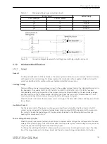
If binary inputs are used for trip circuit monitoring, note that two binary inputs (or one binary input and an
equivalent resistor) are connected in series. The switching threshold must be significantly less than one
half of the rated control voltage.
Contact Mode for Binary Outputs
Input/output modules can have relays with changeover contacts which can be set either as NO or NC. There-
fore it is necessary to rearrange a jumper.
For which relay on which board this applies is described in this Section under “Input/Output Board C–I/O -1”
and “Input/Output Board C–I/O -8”.
Replacing Interfaces
The serial interfaces can only be exchanged in the versions for panel flush mounting and cubicle mounting.
Which interfaces can be exchanged, and how this is done, is described in this Section under the margin title
“Replacing Interface Modules”.
Terminating Resistors for RS485 and Profibus DP (electrical)
For reliable data transmission the RS485 bus or the electrical Profibus DP must be terminated with resistors at
the respective last device on the bus. For this purpose termination resistors are provided on the PCB of the
CCPU- 2 processor board and on the RS485 or PROFIBUS interface module which can be connected via
jumpers. Only one of the three options may be used. The physical location of the jumpers on the PCB is
described in this Section under the margin title “Processor Board C–CPU-2”, and under the margin title “Bus-
Capable Serial Interfaces” for the interface modules. Both jumpers must always be plugged in the same way.
The terminating resistors are disabled on unit delivery.
Spare Parts
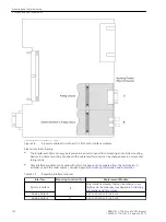
Spare parts can be the battery for storage of data in the battery-buffered RAM in case of a power failure, and
the internal power supply miniature fuse. Their spatial arrangement is shown in
fuse are printed on the board next to the fuse itself. When replacing the fuse, please observe the guidelines
given in the
in chapters “Maintenance” and “Corrective Maintenance”.
Disassembly
Disassembly of the Device
i
i
NOTE
It is assumed for the following steps that the device is not in operation.
!
CAUTION
Caution when changing jumper settings that affect nominal values of the device
As a consequence, the order number (MLFB) and the ratings on the nameplate no longer match the
actual device properties.
²
If changes are necessary under exceptional circumstances, the changes should be clearly and fully
marked on the device. Self adhesive stickers are available that can be used as replacement name-
plates.
To perform work on the printed circuit boards, such as checking or moving switching elements or exchanging
modules, proceed as follows:
3.1.2.2
Mounting and Commissioning
3.1 Mounting and Connections
146
SIPROTEC 4, 7VE61 and 7VE63, Manual
C53000-G1176-C163-3, Edition 10.2017
Содержание SIPROTEC 4 7VE61
Страница 8: ...8 SIPROTEC 4 7VE61 and 7VE63 Manual C53000 G1176 C163 3 Edition 10 2017 ...
Страница 24: ...24 SIPROTEC 4 7VE61 and 7VE63 Manual C53000 G1176 C163 3 Edition 10 2017 ...
Страница 142: ...142 SIPROTEC 4 7VE61 and 7VE63 Manual C53000 G1176 C163 3 Edition 10 2017 ...
Страница 192: ...192 SIPROTEC 4 7VE61 and 7VE63 Manual C53000 G1176 C163 3 Edition 10 2017 ...
Страница 222: ...222 SIPROTEC 4 7VE61 and 7VE63 Manual C53000 G1176 C163 3 Edition 10 2017 ...
Страница 230: ...230 SIPROTEC 4 7VE61 and 7VE63 Manual C53000 G1176 C163 3 Edition 10 2017 ...
Страница 256: ...256 SIPROTEC 4 7VE61 and 7VE63 Manual C53000 G1176 C163 3 Edition 10 2017 ...
Страница 314: ...314 SIPROTEC 4 7VE61 and 7VE63 Manual C53000 G1176 C163 3 Edition 10 2017 ...
Страница 316: ...316 SIPROTEC 4 7VE61 and 7VE63 Manual C53000 G1176 C163 3 Edition 10 2017 ...
Страница 330: ...330 SIPROTEC 4 7VE61 and 7VE63 Manual C53000 G1176 C163 3 Edition 10 2017 ...

