


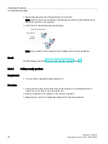


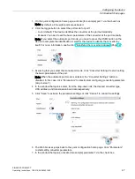

Connecting
4.2 Connecting the converter to the device
SINAMICS CONNECT
34
Operating Instructions, 10/2018, A5E45421408
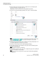
Interface assignment (device side)
RS232 interface on
the device
X121
X122
Description
Pin No. Pin name
Pin No. Pin name
1
PE
17
PE
Protective earth
2
PE4
16
PE8
Protective earth
3
M
15
M
Signal ground
4
RX4
14
RX8
Receive data
5
TX4
13
TX8
Transmit data
6
PE3
12
PE7
Protective earth
7
M
11
M
Signal ground
8
RX3
10
RX7
Receive data
9
TX3
9
TX7
Transmit data
10
PE2
8
PE6
Protective earth
11
M
7
M
Signal ground
12
RX2
6
RX6
Receive data
13
TX2
5
TX6
Transmit data
14
PE1
4
PE5
Protective earth
15
M
3
M
Signal ground
16
RX1
2
RX5
Receive data
17
TX1
1
TX5
Transmit data
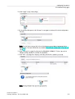
Wiring example
The following takes SINAMICS V20 and X121 port 1 as an example to indicate the wiring
between the converter and the SINAMICS CONNECT.
Note
To achieve better EMC performance, Siemens recommends you to observe the following
when connecting the converter:
•
Use the shielded cable for RS232 communication between the converter and the device.
•
Do not connect the device to the ground via the PE terminal (pin 1 at X121, pin 17 at
X122).
•
Route the signal cables and power cables separately in different cable conduits.
Содержание Sinamics Connect Series
Страница 1: ......
Страница 2: ......
Страница 99: ...Index SINAMICS CONNECT Operating Instructions 10 2018 A5E45421408 97 W Wall mounting 24 27 Weight 85 ...
Страница 100: ......
Страница 101: ......