SIMPRO-100
Commissioning
7
PRIM-2400C
99
7 Commissioning
7.1
Introduction
This section provides guidelines for
commissioning and testing the SIMPRO-100
Relay.
Siemens performs a complete functional check
and calibration of each relay before it is shipped.
This helps to ensure that you receive a relay that
operates correctly and accurately.
Commissioning tests should verify that the relay
is properly connected to the power system and all
auxiliary equipment. Verify control signal inputs
and outputs. Use an ac connection check to verify
that the relay current and voltage inputs are of the
proper magnitude and phase rotation.
Brief functional tests ensure that the relay
settings are correct. It is not necessary to test
every relay element, timer, and function in these
tests.
7.2
Relay
Commissioning
Procedure
7.2.1
Introduction
This procedure is a guideline to help you enter
settings into the SIMPRO-100 Relay and verify
that it is properly connected. Modify the
procedure as necessary to conform with your
standard practices.
Use the commissioning procedure at initial relay
installation; you should not need to repeat it
unless major changes are made to the relay
electrical connections.
7.2.2
Required Equipment
•
SIMPRO-100 Relay, installed and connected
according to your protection design
•
PC with serial port, terminal emulation
software or SIMPRO-PC software, and serial
communication cable (for relay setting entry)
•
SIMPRO-100 Relay Settings Sheets copied
from Appendix F, page 213 or SIMPRO-PC
software settings files and filled out with
settings appropriate to your application and
protection cabinet design
•
AC and dc elementary schematics and wiring
diagrams for this relay installation
•
Continuity tester
•
Protective relay ac test source:
Minimum:
Single-phase voltage plus
single-phase current with ability to control
phase angle between signals
Preferred:
Two- or three-phase voltage plus
three-phase current with ability to control
phase angle between signals
7.2.3
Commissioning Procedure
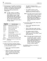
1. Ensure that control power and ac signals are
removed from the SIMPRO-100 Relay by
opening the appropriate breaker(s) or
removing fuses. Isolate the relay TRIP
contact.
2. Verify the accuracy and correctness of the ac
and dc connections by performing
point-to-point continuity checks on the circuits
associated with the SIMPRO-100 Relay.
Содержание SIMPRO-100
Страница 1: ...SIMPRO 100 Motor Protection Relay Instruction Manual Document No PRIM 2400C ...
Страница 12: ...Contents SIMPRO 100 x PRIM 2400C ...
Страница 16: ...Contents SIMPRO 100 xiv PRIM 2400C ...
Страница 42: ...3 SIMPRO PC Software SIMPRO 100 40 PRIM 2400C ...
Страница 50: ...4 Settings Calculation SIMPRO 100 48 PRIM 2400C Figure 4 2 Generic Thermal Limit Curves Cold Motor ...
Страница 100: ...6 ASCII Serial Port Operation SIMPRO 100 98 PRIM 2400C ...
Страница 127: ...SIMPRO 100 Event Analysis 9 PRIM 2400C 125 Figure 9 2 Example SER Report ...
Страница 136: ...10 Maintenance Troubleshooting SIMPRO 100 134 PRIM 2400C ...
Страница 138: ...A Firmware Versions SIMPRO 100 136 PRIM 2400C ...
Страница 147: ...SIMPRO 100 Control Equations Relay Logic B PRIM 2400C 145 Figure B 3 Display Message Variables ...
Страница 157: ...SIMPRO 100 Control Equations Relay Logic B PRIM 2400C 155 Figure B 16 Overvoltage Element Logic ...
Страница 206: ...D SIMPRO PC Compatibility Features SIMPRO 100 204 PRIM 2400C ...
Страница 214: ...E Motor Thermal Element SIMPRO 100 212 PRIM 2400C ...
Страница 230: ...F SIMPRO 100 Relay Settings Sheets SIMPRO 100 228 PRIM 2400C ...
Страница 239: ......

