2
Installation
SIMPRO-100
34
PRIM-2400C
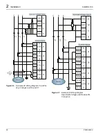
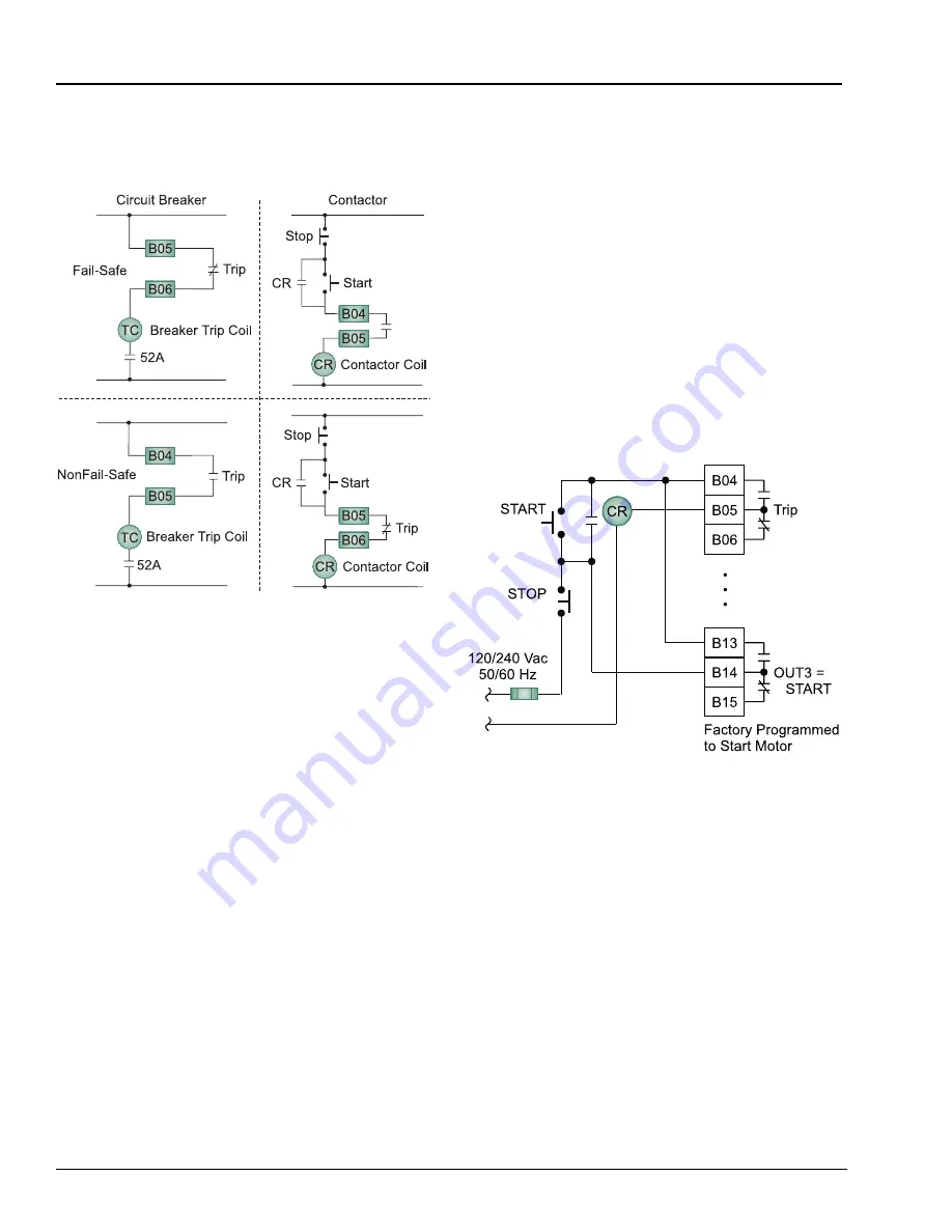
Figure 2.12 shows various wiring methods for
fail-safe and nonfail-safe wiring to control
breakers and contactors.
Figure 2.12
Trip Contact Fail-Safe, NonFail-Safe
Wiring Options
The relay output contacts are fully programmable
using the relay settings described in Appendix B,
page 137. For many applications, the factory
default configuration will provide the desired
performance.
The factory configuration for OUT1 provides an
alarm for selected protection elements such as
the motor thermal element, load loss element,
current unbalance element, and power element
alarms. The normally open output contact of
OUT1 closes if it detects any of these alarm
conditions.
The factory configuration for OUT2 provides an
alarm for RTD-based functions. The relay closes
the normally open output contact if an RTD alarm
temperature is exceeded, if the RTD Bias alarm
picks up, if RTD leads short or open, or if the
relay loses communication with the
SIMPRO-100-RTD Module. This output is
inactive if the relay is not equipped with RTD
inputs.
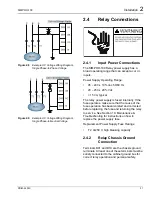
Output OUT3 can be used to start the motor
using the factory default settings as shown in
Figure 2.13.
The ALARM normally closed output contact is a
fail-safe contact. This contact opens while the
relay is in service and closes when:
•
Input power is removed
•
Three incorrect Access Level 2 passwords
are entered
•
Successful Access Level 2 admission is
achieved
•
The relay fails
Figure 2.13
Optional Motor Start Wiring Using
Factory Default Settings for Output
Contact OUT3
Содержание SIMPRO-100
Страница 1: ...SIMPRO 100 Motor Protection Relay Instruction Manual Document No PRIM 2400C ...
Страница 12: ...Contents SIMPRO 100 x PRIM 2400C ...
Страница 16: ...Contents SIMPRO 100 xiv PRIM 2400C ...
Страница 42: ...3 SIMPRO PC Software SIMPRO 100 40 PRIM 2400C ...
Страница 50: ...4 Settings Calculation SIMPRO 100 48 PRIM 2400C Figure 4 2 Generic Thermal Limit Curves Cold Motor ...
Страница 100: ...6 ASCII Serial Port Operation SIMPRO 100 98 PRIM 2400C ...
Страница 127: ...SIMPRO 100 Event Analysis 9 PRIM 2400C 125 Figure 9 2 Example SER Report ...
Страница 136: ...10 Maintenance Troubleshooting SIMPRO 100 134 PRIM 2400C ...
Страница 138: ...A Firmware Versions SIMPRO 100 136 PRIM 2400C ...
Страница 147: ...SIMPRO 100 Control Equations Relay Logic B PRIM 2400C 145 Figure B 3 Display Message Variables ...
Страница 157: ...SIMPRO 100 Control Equations Relay Logic B PRIM 2400C 155 Figure B 16 Overvoltage Element Logic ...
Страница 206: ...D SIMPRO PC Compatibility Features SIMPRO 100 204 PRIM 2400C ...
Страница 214: ...E Motor Thermal Element SIMPRO 100 212 PRIM 2400C ...
Страница 230: ...F SIMPRO 100 Relay Settings Sheets SIMPRO 100 228 PRIM 2400C ...
Страница 239: ......


