


Planning the RF200 system
4.1 Fundamentals of application planning
SIMATIC RF200
System Manual, 07/2017, J31069-D0227-U001-A9-7619
29
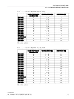
S
a
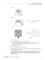
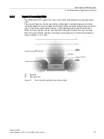
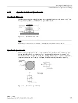
Operating distance between transponder and reader
S
g
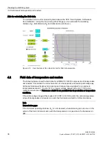
Limit distance (maximum clear distance between upper surface of the reader and the tran-
sponder, at which the transmission can still function under normal conditions)
L
Length of a transmission window
M
Field centerpoint
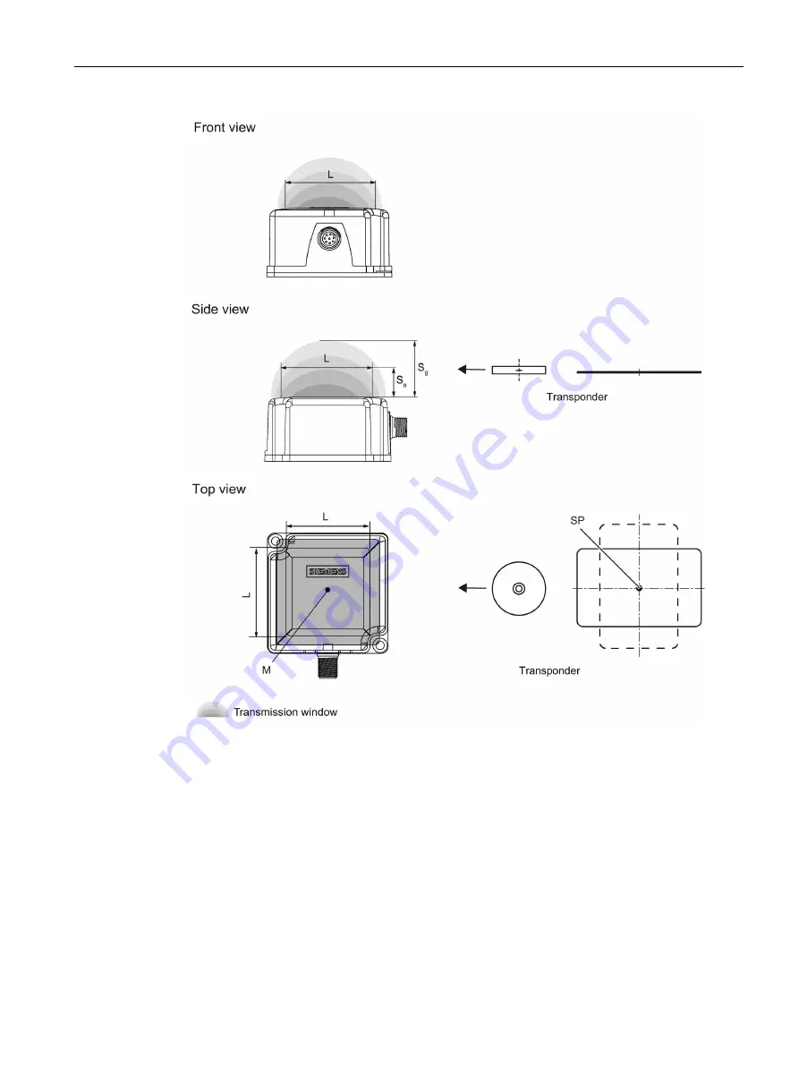
Figure 4-2
RF240R/RF260R transmission window
The transponder can be used as soon as the intersection (SP) of the transponder enters the
area of the transmission window.
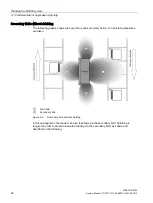
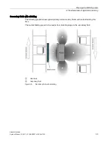
From the diagrams above, it can also be seen that operation is possible within the area
between S
a
and S
g
. The active operating area reduces as the distance increases, and
shrinks to a single point at distance S
g
. Only static mode should thus be used in the area
between S
a
and S
g
.
Содержание SIMATIC RF200
Страница 12: ...Table of contents SIMATIC RF200 12 System Manual 07 2017 J31069 D0227 U001 A9 7619 ...
Страница 18: ...Safety notes SIMATIC RF200 18 System Manual 07 2017 J31069 D0227 U001 A9 7619 ...
Страница 25: ...System overview 3 2 Overview of transponders SIMATIC RF200 System Manual 07 2017 J31069 D0227 U001 A9 7619 25 ...
Страница 26: ......
Страница 102: ...Planning the RF200 system 4 4 Further information SIMATIC RF200 102 System Manual 07 2017 J31069 D0227 U001 A9 7619 ...
Страница 160: ......


