Siemens Energy & Automation, Inc.
29
With the “open on fault” position selected, contact status is as
follows.
Power off - contact is open
Power on - contact closes
Fault occurs or loss of power - contact opens
With the “close on fault” position selected, contact status is
as follows.
Power off - contact is open
Power on - contact is open
Fault occurs - contact closes
The contact remains open for a loss of power.
The factory settings for switch SW1 sections are:
SW1-4: close on fault (switch left)
SW1-3: in line wiring - wye motor (switch left)
SW1-2: no on delay (switch right)
SW1-1: no off delay (switch right)
6.2 LED Indicators
Two LED indicators are located above the potentiometers.
These LED’s indicate controller status and fault conditions as fol-
lows.
LED 1
(Top)
Constant Display
Controller is ready for operation
Single Flashing
FAULT: Main voltage phase loss
Double Flashing
FAULT: EEPROM parity error
LED 2
(Bottom)
Constant Display
Output voltage equals line voltage,
i.e., motor is up to speed
Single Flashing
Output voltage is less than line voltage,
i.e., motor is starting or stopping
Double Flashing
FAULT: Shorted SCR
6.3 Controller Setup
Before the initial startup, set the controls as follows.
1. Set switch SW1 sections in accordance with the application.
2. Set Start Time T1.
This setting is application dependent,
affected by load torque, motor voltage, and total inertia.
The
factory setting is 8, or 15 seconds.
3. Set Initial Voltage U.
The factory setting is 8, or 56% of the
line voltage.
4. Set Stop Time T2. The 0 setting allows the load to coast to
rest. If the soft stop feature is required for the application,
set T2 to the 8 position.
The factory setting is 0.
6.4 Preliminary Checks
With main power disconnect device open and control power off,
check the following.
1. Power and Motor Connections. Check that the controller
has been properly connected to the power source and
motor per figure 10.
2. Control Connections.
Check that control power, the
start/stop control, and applicable devices have been proper-
ly connected to the control terminal board (figure 11).
3. AC Line Power Verification. Verify that each phase of the AC
line power at the disconnect device is within the rated value
of the controller as indicated on the controller nameplate.
4. Ground Check. Use an ohmmeter set to its highest scale
and observe the following.
a. Check for a ground between each controller output ter-
minal (T1, T2, T3) and chassis ground. Each terminal to
ground reading should be over 500K ohms.
b. The measurement between each input terminal (L1, L2,
L3) and ground should be over 500K ohms.
6.5 Initial Energization
1. Temporarily remove run signal connections by opening the
circuit at control terminals A1 and A2.
2. Turn on main AC power and control power to the controller;
LED 1 comes on.
3. Measure input AC voltages L1 to L2, L2 to L3, and L3 to L1.
Voltages should be within the controller’s rated range and
balanced for proper motor operation.
When the line voltages are not equal, unbalanced currents in
the stator windings occur.
A small percentage voltage
unbalance results in a much larger percentage current unbal-
ance.
Consequently, the temperature rise of the motor
operating at a particular load and percentage voltage unbal-
ance is greater than for the motor operating under the same
conditions with balanced voltages. For further information,
refer to NEMA Standard MG 1-14.35.
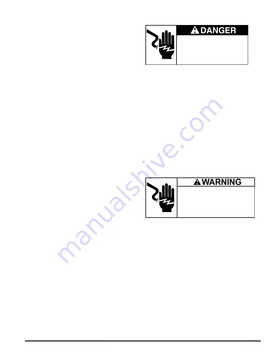
Hazardous voltage.
Will cause death or serious injury.
To avoid electrical shock or burn, turn off
main and control voltages prior to per-
forming preliminary checks.
Hazardous Voltage.
Can cause death, serious injury, or
property damage.
To avoid electrical shock or burn, do not oper-
ate controller with either the cover or the con-
trol terminal finger guard removed.
Содержание SIKOSTART 3RW34
Страница 15: ...Siemens Energy Automation Inc 15 Figure 10 SIKOSTART Power and Motor Connections ...
Страница 16: ...Siemens Energy Automation Inc 16 Figure 11 SIKOSTART Control Connections ...
Страница 42: ...Siemens Energy Automation Inc 42 Figure 27 for 3RW345 Figure 28 for 3RW346 Figure 29 Typical configurations ...


