


SIJECT OP15B Screens
SIJECT 16i Operation Manual
3-35
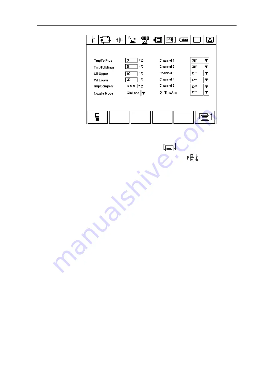
Fig 3-32
Service screen 2.3 – temperature setting
Temperature setting
On service screen 1, press softkey F2
to enter service screen 2 ---
linear scale setting. Then, press softkey F4
so as to enter
temperature setting screen. Temperature channel can be set from 1 to 5,
and temperature can be set accordingly.
Temperature Tolerance Plus --- set the tolerance plus for each
temperature channel.
Temperature Tolerance Minus --- set the tolerance minus for each
temperature channel.
Oil Upper --- set the upper limit of hydraulic oil temperature.
Oil Lower --- set the lower limit of hydraulic oil temperature.
Temperature Compensation --- set the temperature compensation. The
system has been set the compensation before delivery, and it is
unnecessary for users to set it again.
Nozzle Mode --- two modes are available, it can be assigned as close-loop
or open-loop.
Channel 1 --- select or deselect
Channel 2 --- select or deselect
Channel 3 --- select or deselect
Channel 4 --- select or deselect
Channel 5 --- select or deselect
Oil Temperature Alarm --- If oil temperature alarm is selected: when the
upper/lower limit of oil temperature has been set, there is no alarm if oil
temperature is within the specification and alarm occurs if it is out of
specification.
Содержание SIJECT 16i
Страница 1: ...User Manual User Documentation Software Version 1 11 2003 Edition SIJECT 16i Operation Manual ...
Страница 6: ......
Страница 26: ......


