6
Installation Checks and Initial Functional Tests
crank clockwise to rack the circuit breaker from the
disconnect position to the Test position.) If the racking
crank is not of the “Captive” type, constant inward
pressure is required during racking to maintain engage-
ment with the racking mechanism.
3. With the circuit breaker in the Test position and
OPEN, de-energize control power to the circuit breaker.
Figure 1
shows the location of control power discon-
nects in a normal unit.
4. Perform the Spring Discharge Check, and verify that
the circuit breaker is OPEN and the closing spring indi-
cator shows DISCHARGED.
5. Insert the two extension rails into the fixed rails. Be
sure the extension rails are properly secured in place.
(This can be done at step 7 if preferred.)
6. Insert the racking crank on the racking screw on the
front of the circuit breaker cell, and push in, as
described in step 2. Rotate the racking crank counter-
clockwise until the circuit breaker is in the Disconnect
position.
7. If you have not yet installed the extension rails, do
so now. Note that some difficulty may be experienced
installing the extension rails if the circuit breaker is in
the Disconnect position. If difficulty is encountered,
rack the circuit breaker to the Test position, install the
extension rails, and then rack the circuit breaker to the
Disconnect position.
8. Move the circuit breaker release latch to the left and
pull the circuit breaker out from the Disconnect
position. The circuit breaker is now free to be rolled out
of the two extension rails using the handles on the
front of the circuit breaker.
9. Remove the circuit breaker from the two extension
rails using the approved Siemens breaker lifting device
or lifting sling.
10. Lift the two extension rails and withdraw them
from the switchgear.
Heavy Weight.
Can cause death, serious injury, or
property damage.
Always use extension rails to remove or
install circuit breaker in the upper cell or in
cells not installed at floor level.
WARNING
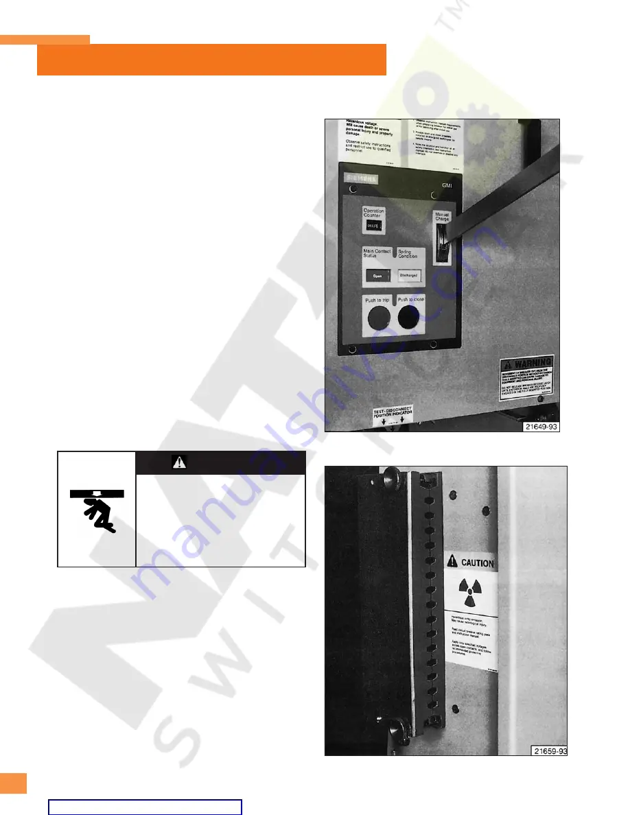
Figure 6:
Manual Charging of Closing Springs.
Figure 7:
Split Plug Jumper Connected to Circuit Breaker.


