31
Overhaul
Introduction
For following procedures along with the troubleshooting
charts at the end of this section, provide maintenance
personnel with a guide to identifying and correcting
possible malfunctions of the GMI vacuum circuit breaker.
Circuit Breaker Overhaul
Table 5
lists the recommended overhaul schedule for GMI
circuit breakers operating under ANSI usual conditions.
When actual operating conditions are more severe, overhaul
periods should occur more frequently. The counter on the
front panel of the circuit breaker records the number of
operations.
Replacement at Overhaul
The following components are replaced during an overhaul
of the circuit breaker, when required:
• Vacuum interrupters as determined by vacuum
integrity test, contact erosion, or after 30,000
operations (10,000 for VS-15050).
• Spring charging motor brushes should be replaced
after 10,000 operations (reference kit 18-658-612-
886).
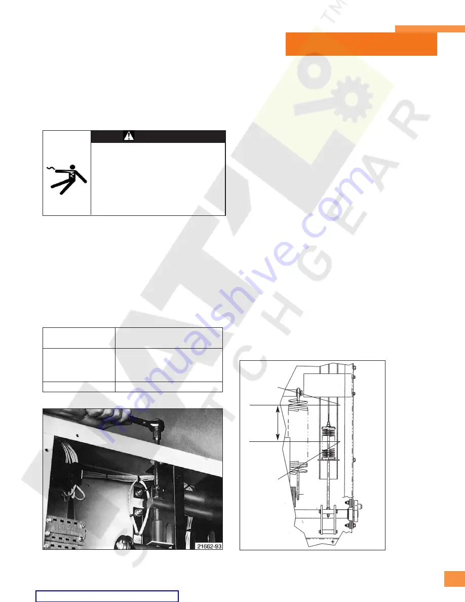
Replacement of Closing Springs
Figure 38
shows the use of a 3/4 inch socket wrench to
relieve spring tension on the closing springs. The top cover
of the circuit breaker has openings providing access to the
tensioning bolts. Turning the left and right hand support
bolts counterclockwise relieves spring tension.
For early models of the GMI circuit breaker, once tension
has been relieved, retaining ring pliers are needed to
remove the top and bottom retaining rings attaching each
spring to its cross-arm support shaft and its crank arm.
For later models of the GMI circuit breaker, the lower spring
hangers are fastened to the crank arms, using hex socket
shoulder bolt and nut. The nut is applied using thread
locking adhesive, Loctite 271, with Loctite type T primer.
When one or both springs are reinstalled, be sure the
support bolts are inserted inside their support bolt bushing.
These bushings maintain the correct tension on the closing
springs. Replace all retaining rings during the re-assembly.
C
Ciirrccu
uiitt
N
Nu
um
mb
be
err o
off
B
Brre
ea
ak
ke
err T
Ty
yp
pe
e
C
Cllo
ossiin
ng
g O
Op
pe
erra
attiio
on
nss
5-GMI-350
5-GMI-50
5,000 operations
15-GMI-1000
15-GMI-50
All others
10,000 operations
Figure 38:
Use of Socket Wrench to Release Tension on
Closing Springs.
Figure 39:
Removal of Opening Spring.
FACTORY
ADJUSTED
DIMENSION
LOWER
SPRING
CAP
UPPER
SPRING
CAP
Hazardous voltage and high speed mechan-
ical parts.
Can cause death, serious injury, or property
damage.
All replacement of circuit breaker components
must be performed with the circuit breaker
completely de-energized and the springs
discharged.
WARNING
Table 5 – Overhaul Schedule
ANSI Usual Conditions
Maintenance Based Upon Number of Closing Operations


