49
Appendix
N
No
om
miin
na
all
R
Ra
an
ng
ge
e
A
Am
mp
pe
erre
ess
C
Ch
ha
arrg
giin
ng
g
C
Cllo
osse
e
T
Trriip
p
A
Am
mp
pe
erre
ess
1
1
A
Am
mp
pe
erre
ess
1
1
R
Ru
un
n ((A
Av
vg
g..))
1
1
IIn
nrru
ussh
h ((P
Pe
ea
ak
k))
1
1
S
Se
ecco
on
nd
dss
48 VDC
38-56
28-56
10
2
10
2
8.5
15
10
125 VDC
100-140
70-140
4
4
2.7
10.2
8
250 VDC
200-280
140-280
3
3
1.3
2.4
8
120 VAC
104-127
104-127
4
–
3.3
10.6
8
240 VAC
208-254
208-254
3
–
1.7
7.1
8
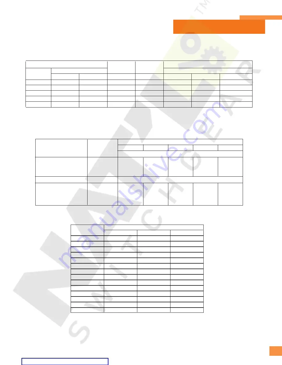
Table A-2 – 5kV, 7.2kV and 15kV Type GMI Circuit Breaker Control Data
Typical Spring Release (Close Coil), Trip Coil and Spring Charging Motor Characteristics
Control Voltages, ANSI C37.06 Table 10
S
Sp
prriin
ng
g C
Ch
ha
arrg
giin
ng
g M
Mo
otto
orr
Close Coil
T
Trriip
p C
Co
oiill
Table A-3 – Interrupting Capacity Auxiliary Switch Contacts
Control Circuit Voltage
Type
Auxiliary
Switch
Continuous
Current
Amperes
120 VAC
240 VAC
48 VDC
125 VDC
250 VDC
Non-Inductive Circuit Interrupting Capacity in Amperes
Breaker Auxiliary Switch
20
20
20
20
10
2
TOC Auxiliary Switch
15
15
10
0.5
0.5
0.2
MOC Auxiliary Switch
20
15
10
10
10
5
Inductive Circuit Interrupting Capacity in Amperes
Breaker Auxiliary Switch
20
20
20
20
10
2
TOC Auxiliary Switch
15
15
10
0.5
0.5
0.2
MOC Auxiliary Switch
20
15
10
10
10
5
Table A-4 – Circuit Breaker Weights [lbs (kg)]
Breaker Type
Continuous Current Rating
1200 A
2000 A
3000 A
5-GMI-250
385 (175)
425 (193)
—
5-GMI-31
385 (175)
425 (193)
—
5-GMI-350
440 (200)
550 (250)
575 (261)
5-GMI-40
440 (200)
550 (250)
575 (261)
5-GMI-50
450 (205)
560 (255)
585 (266)
7-GMI-500
440 (200)
550 (200)
585 (266)
7-GMI-40
440 (200)
550 (200)
585 (266)
15-GMI-500
415 (188)
455 (206)
—
15-GMI-25
415 (188)
455 (206)
—
15-GMI-750
425 (193)
465 (211)
580 (263)
15-GMI-31
425 (193)
465 (211)
—
15-GMI-1000
450 (205)
560 (255)
585 (266)
15-GMI-40
450 (205)
560 (255)
585 (266)
15-GMI-50
460 (210)
570 (260)
595 (271)
1
Current at nominal voltage.
2
23A for coils supplied up to mid-1993.


