9
Installation Checks and Initial Functional Tests
Introduction
The Type GMI vacuum circuit breaker is of drawout
construction designed for use in medium voltage, metal-
clad switchgear. The GMI circuit breaker conforms to the
requirements of ANSI standards C37.20.2, C37.04, C37.06,
C37.09 and C37.010.
GMI circuit breakers consist of three vacuum interrupters, a
stored energy operating mechanism, necessary electrical
controls and interlock devices, disconnect devices to
connect the circuit breaker to both primary and control
power and an operator housing. On some circuit breaker
ratings, insulating barriers are located between the
vacuum interrupters or along the sides.
This section describes the operation of each major
subassembly as an aid in the operation, installation, main-
tenance and repair of the GMI vacuum circuit breaker.
Vacuum Interrupters and Primary Disconnects
The operating principle of the GMI vacuum interrupter is
simple.
Figure 11
is a cutaway view of a typical vacuum
interrupter. The entire assembly is sealed after a vacuum is
established. The interrupter stationary contact is
connected to the upper disconnect stud of the circuit
breaker. The interrupter movable contact is connected to
the lower disconnect stud and driving mechanism of the
circuit breaker. The metal bellows assembly provides a
secure seal around the movable contact, preventing loss of
vacuum while permitting vertical motion of the movable
contact.
When the two contacts separate an arc is initiated which
continues conduction up to the following current zero. At
current zero, the arc extinguishes and any conductive
metal vapor which has been created by and supported the
arc condenses on the contacts and on the surrounding
vapor shield. Contact materials and configuration are opti-
mized to achieve arc control and to minimize switching
disturbances.
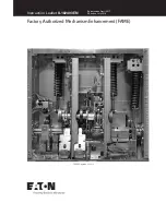
Figure 10:
Front View of GMI Circuit Breaker.
Figure 11:
Cutaway View of Typical Vacuum Interrupters.


