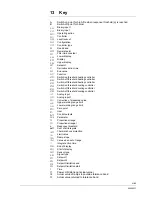
13 Key
A
Switch-on point for high-fire when response threshold (q) is reached
B
Switch-off point for burner
bin1
Binary input 1
binF
Binary input
CACt
Operating action
Cntr
Controller
CodE
Level lockout
ConF
Configuration
CtYP
Controller type
db
Dead band
dECP
Decimal point
dF1
Filter time constant
diSL
Lower display
diSP
Display
diSU
Upper display
dSP
Setpoint
dt
Derivative action time
End
End value
FnCt
Function
HYS1
Switch-on threshold heating controller
HYS2
Switch-off threshold heating controller
HYS3
Switch-off threshold heating controller
HYS4
Switch-on threshold cooling controller
HYS5
Switch-off threshold cooling controller
HYS6
Switch-off threshold cooling controller
InP
Analog input
InP1
Analog input 1
OFF1
Correction of measured value
oLHi
Upper working range limit
oLLo
Lower working range limit
OPnt
Zero point
OPr
User
OutP
Control outputs
PArA
Parameter
Pb
Proportional range
Pb1
Proportional range 1
q Response
threshold
qeff
Sum of all integrals
rAFC
Thermal shock protection
rAL
Limit value
rASL
Ramp slope
rOut
Value when out of range
rt
Integral action time
SCH1
End of display
SCL1
Start of display
SEn1
Sensor type
SiGn
Signal type
SP1
Setpoint 1
SP2
Setpoint 2
SPH
Setpoint limitation end
SPL
Setpoint limitation start
t Time
t1
Power ON (startup at actual value)
t2
Actual value of ramp stop outside tolerance band
t3
Actual value returned to tolerance band
61/68
20089337
Содержание RWF 50.2
Страница 2: ...20089337 Translation of the original instructions ...
Страница 4: ...2 68 20089337 ...
Страница 6: ...4 68 20089337 ...
Страница 14: ...1 4 Block structure Only RWF50 3 Only RWF50 2 Air damper control Figure 1 Block structure 12 68 20089337 ...
Страница 62: ...60 68 20089337 ...
Страница 66: ...64 68 20089337 ...
Страница 69: ......
Страница 70: ......
Страница 71: ......


