


81/130
Siemens Building Technologies
Basic Documentation RVD230
CE1P2383en
HVAC Products
21 Function block LPB parameters
27.05.2004
21
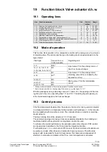
Function block LPB parameters
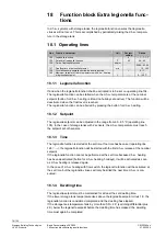
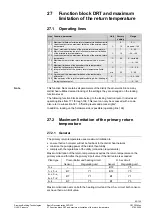
21.1 Operating
lines
Line
Function, parameter
Unit
Factory
setting
Range
131
Device number for bus address
0
0…16
132
Segment number for bus address
0
0…14
133
Clock mode
0
0…3
134
Bus power supply, operating mode and status indication
A
0 / 1 / A
135
Outside temperature source
A
A / 00.01… 14.16
136
Gain of locking signal
%
100
0…200
137
Response to uncritical locking signals from the data bus
1
0 / 1
146
Pump kick
1
0 / 1
21.2 LPB
parameters
21.2.1 Addressing the devices
Each device connected to the data bus (LPB) requires an address. This address is
comprised of a device number (1…16, operating line 131) and a segment number
(0…14, operating line 132).
In an interconnected plant, each address may be assigned only once. If this is not ob-
served, proper functioning of the entire plant cannot be ensured. In that case, an error
message will be generated (error code 82).
If the controller is operated autonomously (with no bus), both the device number and
the segment number must be set to zero.
Since the device address is also associated with control processes, it is not possible to
permit all possible device addresses in all types of plant:
Primary controller plant types 5–x, 6–x and 7–2 must be given device number 1.
If an inadmissible address has been entered for the selected type of plant, an error
message will appear (error code 140).
For detailed information about the addressing of devices, refer to Data Sheet N2030.
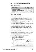
21.2.2 Source of time of day
Depending on the master clock, different sources for the time of day can be used. The
source must be entered on the controller on operating line 133, as a digit (0…3):
0 = autonomous clock in the RVD230
1 = time of day from the bus; clock (slave) with no remote readjustment
2 = time of day from the bus; clock (slave) with remote readjustment
3 = time of day on the bus; central clock (master)
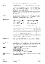
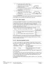
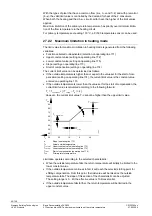
The effect of the individual entries is as follows:
Input Effect
0
•
The time of day on the controller can be
readjusted
•
The controller's time of day is not matched
to the system time
Controller time
System time
Adjustment
1
•
The time of day on the controller cannot be
readjusted
•
The controller's time of day is automatically
and continually matched to the system time
System time
Adjustment
Controller time