43/130
Siemens Building Technologies
Basic Documentation RVD230
CE1P2383en
HVAC Products
12 Function block Space heating
27.05.2004
2462
D
06
S
Impact of the room temperature setpoint change on the flow tem-
perature setpoint
∆
w
R
Change of room temperature setpoint
s heating
curve
slope
∆
w
VT
Change of flow temperature setpoint
The flow temperature setpoint change
∆
w
VT
is calculated according to the following
formula:
∆
w
VT
=
∆
w
R
× ( s × 0.1 + 1 )
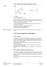
12.3 Heating curve
With both types of weather-compensated flow temperature control (with / without room
temperature influence), the heating curve ensures the assignment of the flow tempera-
ture setpoint to the outside temperature. Its slope is to be set on operating line 5.
T
AM
T
V
s
=
23
81
D
0
5
110
100
90
80
70
60
50
40
30
20
20
15
10
5
0
-5
-10
-15
-20
-25
-30
-35
40
35 32,5 30
27,5
25
22,5
20
17,5
15
12,5
10
7,5
5
2,5
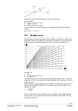
Heating curve
s Slope
T
AM
the composite outside temperature
TV Flow
temperature
The heating curve has a fixed tilting point at an outside temperature of 22 °C and a flow
temperature of 20 °C. It can be set around this tilting point in the range from 2.5 to 40 in
increments of 0.5.
Each heating curve has a substitute line which intersects the tilting point and ”its” heat-
ing curve at an outside temperature of 0 °C. Its slope is set on the controller and is
calculated as follows:
10 ×
∆
TV
s =
∆
T
AM
The use of a substitute line is required because the heating curve is slightly deflected.
This is necessary to compensate for the non-linear radiation characteristics of the dif-
ferent types of radiators.

