33/116
Smart Infrastructure
Basic Documentation LME7...
CC1P7105enr
4
Technical
data
24.07.2020
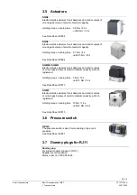
4.5 Actuators
CLOSE / ignition position / OPEN
terminal
X2-09 pin 1, X2-09 pin 2, X2-
09 pin 3
1 mio. switching
cycles
1 mio. switching
cycles
Rated voltage
AC 120 V 50
/
60 Hz AC 230 V 50
/
60 Hz
Rated current
0.1 A
0.1 A
Power
factor
Cos
0.6 Cos
0.6
Output K2/2 X2-09 pin 7
AC 120 V 50/60 Hz AC 230 V 50/60 Hz
Nominal current
Max. 1 A
Max. 1 A
Power
factor
Cos
>0.4
Cos
>0.4
Feedback via input X2-09 pin 8 on the LME depending on the current load of the
actuator switching contact used (e.g. cam V2)!
4.6 Cross-sectional
areas
The cross-sectional areas of the mains power lines (L, N, and PE) and, if required, the
safety loop (safety temperature limiter, water shortage, etc.) must be sized for rated
currents according to the selected external primary fuse. The cross-sectional areas of
the other cables must be sized in accordance with the primary fuse for the LME7 (max.
6.3 AT).
Caution!
Risk of damage to the switching contacts!
If the external primary fuse (Si) is blown due to overload or short-circuit at the
terminals, the LME7 must be replaced.
Min. cross-sectional area
0.75 mm²
(single- or multicore to VDE 0100)
Cable insulation must be suited for the respective temperature and environmental
conditions!

