


17/116
Smart Infrastructure
Basic Documentation LME7...
CC1P7105enr
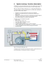
2 System makeup / function description
24.07.2020
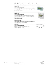
The LME7 system components (AZL2) are connected directly to the LME7 via BCI. All
safety-related digital inputs and outputs of the system are supervised by a contact
feedback network. For intermittent operation, the ionization probe and the QRA2, QRA4
or QRA10 (optional) can be used in connection with the LME7. The LME7 is operated
and parameterized via the AZL2 or ACS410. The AZL2 features an LCD and menu-
driven operation, offering straightforward operation and targeted diagnostics. When
making diagnostics, the display shows operating states as well as the type and time of
errors. The various parameterization levels of the burner/boiler manufacturer and
heating engineer are password-protected against unauthorized access. Simple settings
that the plant operator can make on site do not require a password.
Multicolor indication for operating state and fault status messages via 3-color LED
Diagnostics of cause of fault via blink code
Extensive service, fault and operating state information via built-in 3 x 7 segment
display
Extensive service, fault and operating state information via BCI and AZL2
2.1 Features
-
Undervoltage detection
-
Electrical remote reset facility
-
Accurate control times thanks to digital signal handling
-
Multicolor indication of fault status and operating state messages
-
Air pressure supervision with function check of air pressure switch during start and
operation
-
Restart limitation
-
Controlled intermittent operation after max. 24 hours of continuous operation (can
be parameterized via parameter 239) (depending on the PME7)
-
BCI
-
Unit parameter adjustable either via the AZL2 or ACS410
-
Plug-in space for PME7
Only LME71.../LME73...:
-
Indication of program sequence
The following items are integrated into the LME7:
Burner
control
BC interface for connecting an AZL2 or PC
Lockout reset button (info button)
3 multi color signal lamp LED for operations and fault notifications
Optional: Analog inputs for load controller DC 0...10 V, DC 0/4...20 mA, 0...135
Ω
Interface for PME7
Only LME71.../LME73...:
Optional: 3 x 7 segment display for fault and state information's and parameter
display
Control for one actuator
Indication and
diagnostics