I-T-E Handle Padlocking Device (MN6HPL)
2 7
General
The padlocking device, MN6HPL, consists of the handle
blocking device (3) and an additional component (4) that
permits padlock securement of the circuit breaker handle in
the OFF position (Figure 3). Field modification of the handle
blocking device will also permit padlock securement of the
circuit breaker handle in the ON position.
Installation of Handle Blocking Device
A.
Turn power off supplying circuit breaker
B.
Turn circuit breaker off.
C.
Loosen the two screws (1) (#10-32 x 3/8 in.) so that the
blocking device can be positioned and fully seated over
the toggle handle, as shown in Figure 1.
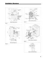
Figure 1
D.
With a screwdriver, turn the screws so they enter the
blind holes molded in each side of the toggle handle.
Tighten the two screws evenly so that when they engage
the bottom of the blind holes, they project an equal
distance of .094 in. (Figure 2) above the tapped surface.
Do not over torque. Maximum torque 2 in. Ib.
Figure 2
Installation of Handle Padlocking Device
To install the padlocking device, first complete the applicable
Handle Blocking Installation Instructions.
A.
Slide the retaining slots of the padlocking component (4)
over the handle blocking device retaining screws. Posi-
tion the padlocking component at the angle shown in
Figure 3.
Figure 3
B.
Rotate the padlocking component until it is positioned
over the handle blocking device, as shown in Figure 4.
Install up to three padlocks, as required.
Figure 4
Содержание I-T-E Sensitrip MD Series
Страница 2: ......
Страница 6: ...4 I T E Sensitrip Digital Circuit Breaker MD and ND Frame Outline Drawings 1 3 Pole ...
Страница 8: ...6 MD and ND Frame Trip Adjustments ...
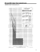
Страница 12: ...10 MD and ND Frame Time Current Curve 600 1000A With Short Time Delay Set on Fixed Time ...
Страница 13: ...MD and ND Frame Time Current Curve 11 1200A With Short Time Delay Set on Fixed Time ...
Страница 14: ...12 MD and ND Frame Time Current Curve 600 100A With Short Time Delay Set on I2 t ...
Страница 15: ...MD and ND Frame Time Current Curve 13 1200A With Short Time Delay Set on I2 t ...
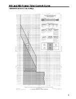
Страница 16: ...14 MD and ND Frame Time Current Curve 600 100A Without Short Time Settings ...
Страница 17: ...MD and ND Frame Time Current Curve 15 1200A Without Short Time Settings ...
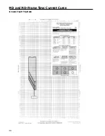
Страница 18: ...16 MD and ND Frame Time Current Curve Ground Fault Trip Data ...
Страница 19: ...MD and ND Frame Time Current Curve 17 Example ...
Страница 20: ...18 MD and ND Frame Let Thru Curves ...
Страница 31: ...Installation Diagrams 29 ...
Страница 35: ...I T E Mechanical Interlock M15404 33 Figure 7 ...
Страница 41: ...Installation Diagrams 39 ...
Страница 49: ...Installation Diagrams 47 ...
Страница 50: ...48 I T E Panelboard Connecting Straps 1 ...
Страница 53: ...Installation Diagrams 51 ...

