52
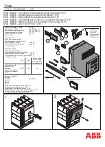
MD and ND-Frame Neutral Sensing Transformer
General
The I-T-E Neutral Sensing Transformers are available in 600,
700, 800, 1000, and 1200 amp ratings. The neutral sensing
transformer is designed to accept either (3) 750 mcm (max)
cables or (1 ) 4 in. x 3/4 in. (max) bus bar. The transformer can
be mounted with either side up. Transformer terminals X1 and
X2 are marked for standardization only. These terminal con-
nectors can be made either by crimp ring or with bare
conductors (16 AWG max). The label provided denoting the
addition of the neutral sensing transformer is to be affixed to
the side of the breaker.
NOTE: This instruction outlines the recommended installation
procedure for the N06SMDA, N07SMDA, N08SMDA,
N10SNDA, and N12SNDA.
AAAA
AAAA
AAAA
AAAA
AAAA
AAAA
AAA
AAA
AAAA
AAAA
AAAA
AAAA
AAAA
AAAA
AAA
AAA
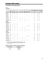
Ampere Rating (In)
Catalog Numbers
600
N06SMDA
700
N07SMDA
800
N08SMDA
1000
N10SNDA
1200
N12SNDA
Caution:
The ampere rating of the transformer must be the
same as the circuit breaker Max. Rating (In) for proper
operation. Failure to match neutral sensor ampere rating
with breaker ampere rating may result in nuisance trip-
ping or no trip due to ground fault which could result in
property damage.
Bus Bar System Mounting.
A.
Turn OFF power feeding this device before starting the
installation.
B.
Also Turn OFF any line power within the immediate
vicinity to prevent the incidental or accidental contact of
tools by the installer.
C
Select a position which is as close as possible to the
circuit breaker trip unit.
D.
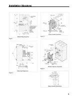
Drill or punch four 0.313 in. diameter holes in the hole
pattern (Figure 1).
Figure 1
NOTE: Mount screws (3) in direction shown (Figure 2) to
maintain electrical spacing.
Figure 2
E.
Connect leads from terminal X1 and X2 (5) on the neutral
sensing transformer (2) using the 10-32 terminal screws
(6) provided.
Содержание I-T-E Sensitrip MD Series
Страница 2: ......
Страница 6: ...4 I T E Sensitrip Digital Circuit Breaker MD and ND Frame Outline Drawings 1 3 Pole ...
Страница 8: ...6 MD and ND Frame Trip Adjustments ...
Страница 12: ...10 MD and ND Frame Time Current Curve 600 1000A With Short Time Delay Set on Fixed Time ...
Страница 13: ...MD and ND Frame Time Current Curve 11 1200A With Short Time Delay Set on Fixed Time ...
Страница 14: ...12 MD and ND Frame Time Current Curve 600 100A With Short Time Delay Set on I2 t ...
Страница 15: ...MD and ND Frame Time Current Curve 13 1200A With Short Time Delay Set on I2 t ...
Страница 16: ...14 MD and ND Frame Time Current Curve 600 100A Without Short Time Settings ...
Страница 17: ...MD and ND Frame Time Current Curve 15 1200A Without Short Time Settings ...
Страница 18: ...16 MD and ND Frame Time Current Curve Ground Fault Trip Data ...
Страница 19: ...MD and ND Frame Time Current Curve 17 Example ...
Страница 20: ...18 MD and ND Frame Let Thru Curves ...
Страница 31: ...Installation Diagrams 29 ...
Страница 35: ...I T E Mechanical Interlock M15404 33 Figure 7 ...
Страница 41: ...Installation Diagrams 39 ...
Страница 49: ...Installation Diagrams 47 ...
Страница 50: ...48 I T E Panelboard Connecting Straps 1 ...
Страница 53: ...Installation Diagrams 51 ...


