38
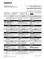
I-T-E Rotary Handle Operator
Types 1, 3R, 4, 4X, 12
Standard Depth (RHONSD)
Variable Depth (RHONVD)
General
When properly installed, the rotary handle operator provides
single point latching of the enclosure door For maximum
protection against unauthorized entry into the enclosure,
additional latching means should be provided. The handle can
be padlocked in the OFF position with up to three 5/16 in.
padlocks. The breaker operator can also be padlocked in the
OFF position.
Drilling of Enclosure
A.
Turn off and lock out all power supplying the circuit
breaker before installing.
B.
Catalog number RHONSD standard depth shafts are for
use in 11 in. deep enclosures. Refer to minimum K
dimension in Figure 2. Catalog number RHONVD variable
depth shafts are used for all other enclosure depths up to
20.66 in. deep. Shafts are cut to length L as shown in
Figure 2.
C.
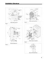
Place circuit breaker mounting holes (Figure 1) in breaker
mounting surface (1) and handle mounting holes in enclo-
sure door (2) (Figure 2).
Installation of Breaker and Breaker Operator
A.
Loosen four breaker terminal shield screws (3), remove
both terminal shields (4) from the line and load side of the
circuit breaker and mount the circuit breaker to the
enclosure panel using four 3/8-16 in. mounting screws,
washers and nuts (5) provided in hardware kit. Tighten
mounting hardware securely (Figure 4).
B.
Replace the breaker terminal shields on the load and line
side of the circuit breaker and secure with four breaker
terminal shield screws. Tighten to 12 in. Ib.
C.
Remove the second screw (6) from each side of the
circuit breaker cover (located above the circuit breaker
handle) (Figure 4).
D.
Position the breaker operator (7) on the circuit breaker
and attach at the top using the two #10-32 x 1.00 pan
head screws (8) and lock washers. Torque these screws
to 25 in. Ib. Attach the breaker operator at the bottom
using the four #10-14 x .500 Phillips head thread forming
screws (9). Torque to 20 in. Ib. maximum (Figure 4).
NOTE: The mounting holes are under the labels.
Installation of Shaft
A.
If applicable, cut variable length shaft to length required
L=K 8.38. B. Insert the shaft (10) into the square hole (11)
in the crank (12) of the breaker operator and tighten the
two 1/4-20 x .375 set screws (13) to 70 in. Ib.
NOTE: Groove in shaft fits over ridge along side of hole. (Figure
4).
Installation of Handle
A.
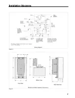
Place handle into OFF position. Attach the handle (14)
and gasket (15) to the enclosure door with the four square
neck bolts (16), lock washers and nuts supplied. Tighten
nuts to 75 in. Ib. (Figure 3).
Check operation
A.
Close enclosure door Confirm that handle interlocks with
the guide cone (17) (Figure 4) of the shaft to hold the door
closed in all handle positions except OPEN/RESET Check
proper operation of the circuit breaker ON/OFF and
RESET
To open the enclosure door when the breaker is in the ON
position, rotate the screw slot (18) on the handle plate (19)
counterclockwise. This procedure will defeat the interlock
(Figure 3).
Padlocking
A.
To lock handle in the OFF position, pull the lockplate (20)
from the end of handle into the grooves on the handle
plate located at the interlock defeater screw and insert
and attach padlock(s) through slot of lockplate (see
photo).
B.
The breaker operator can be padlocked by inserting
padlock through the lower slots used as a path for the
crank arm (see photo).
Содержание I-T-E Sensitrip MD Series
Страница 2: ......
Страница 6: ...4 I T E Sensitrip Digital Circuit Breaker MD and ND Frame Outline Drawings 1 3 Pole ...
Страница 8: ...6 MD and ND Frame Trip Adjustments ...
Страница 12: ...10 MD and ND Frame Time Current Curve 600 1000A With Short Time Delay Set on Fixed Time ...
Страница 13: ...MD and ND Frame Time Current Curve 11 1200A With Short Time Delay Set on Fixed Time ...
Страница 14: ...12 MD and ND Frame Time Current Curve 600 100A With Short Time Delay Set on I2 t ...
Страница 15: ...MD and ND Frame Time Current Curve 13 1200A With Short Time Delay Set on I2 t ...
Страница 16: ...14 MD and ND Frame Time Current Curve 600 100A Without Short Time Settings ...
Страница 17: ...MD and ND Frame Time Current Curve 15 1200A Without Short Time Settings ...
Страница 18: ...16 MD and ND Frame Time Current Curve Ground Fault Trip Data ...
Страница 19: ...MD and ND Frame Time Current Curve 17 Example ...
Страница 20: ...18 MD and ND Frame Let Thru Curves ...
Страница 31: ...Installation Diagrams 29 ...
Страница 35: ...I T E Mechanical Interlock M15404 33 Figure 7 ...
Страница 41: ...Installation Diagrams 39 ...
Страница 49: ...Installation Diagrams 47 ...
Страница 50: ...48 I T E Panelboard Connecting Straps 1 ...
Страница 53: ...Installation Diagrams 51 ...


