2 8
I-T-E Plug-In Adapters
NOTE: Plug-in adapters are for use only with MD-Frame.
General
A complete plug-in installation requires one line end adapter
assembly (consisting of mounting block, tulip connectors and
associated hardware), one load end adapter assembly and
one switchboard mounting plate. The switchboard mounting
plate is optional and can be replaced by other mounting
means to suit customers’ requirements.
AAAA
AAAA
AAAA
AAAA
AAAA
AAAA
AAAA
AAAA
AAAA
AAAA
AAAA
AAAA
AAAA
AAAA
AAAA
AAAA
AAAA
AAAA
AAAA
AAAA
AAAA
AAAA
AAAA
AAAA
AAAA
AAAA
AAAA
AAAA
AAAA
AAAA
AAAA
AAAA
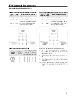
No. of Poles
Line End
Adapter
Load End
Adapter
Switchboard
Mtg. Pan
3
PC5663
PC5663
PL9698
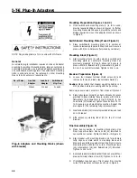
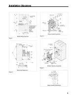
Mounting Preparation (Figures 1 and 2)
A.
If the switchboard mounting plate (1 ) is to be used,
provide required drilling as shown in Figure 1. B. If other
mounting means are to be used, provide the cutouts and
drilling required to mount the adapter blocks as shown
in Figure 2.
Switchboard Mounting Plate (If used Figure 3)
A.
Place switchboard mounting plate (1) in position at
location previously prepared in Step A above. Secure in
place with 5/16 in. hardware (furnished by customer).
A.
Align mounting block (2) with cutouts in switchboard
mounting plate (or customer’s mounting means as
previously prepared in Step B above) and secure in
place with 3/8 in. flatwashers (3), lockwashers (4), and 3/
8-16 in. hex nuts (5) furnished. Tighten to 216 in.-lb.
Breaker Preparation (Figure 4)
A.
Loosen four breaker terminal shield screws (6) and
remove both line and load side terminal shields (7).
Caution:
Make certain that breaker operating handle is in
OFF position before proceeding with the next step.
Remove pressure wire connectors from breaker if present.
B.
Place tulip clip assembly (8) on back of breaker in recess
provided in base molding. Secure in place with 5/16 in.
flatwashers (9), lockwashers (10) and 5/16-18 in. hex
head bolts (11) furnished. Tighten these bolts to 72 in.-
lb. to assure a good electrical connection. Repeat this
procedure for the remaining tulip clip assemblies.
C.
Insert end shields (12) into slots provided at line and load
end of breaker.
D.
Affix accessory warning label (13) to top of circuit
breaker.
A.
Make bus-connection to mounting block studs. Use
Only Copper Bus Bars. Use hex nuts (14) furnished to
secure this connection. Tighten to 2400 in.-lb. (Figure 5).
B.
Align breaker with mounting blocks and force female
tulip clips over male studs in mounting block until
breaker base bottoms against mounting block. Secure
breaker in place with 3/8-16 x 1~/2 in. mounting screws
(15), lockwashers (16), and flatwashers (17) furnished.
Tighten to 216 in.-lb.
C.
Replace breaker terminal shields (7) and secure with four
breaker terminal shield screws (6). Tighten to 12 in.-lb.
D.
If installation requires use of front panel trim, provide
cutout for breaker escutcheon as shown in Figure 6.
Plug-in Adapters and Mounting Blocks (shown
with breaker)
Содержание I-T-E Sensitrip MD Series
Страница 2: ......
Страница 6: ...4 I T E Sensitrip Digital Circuit Breaker MD and ND Frame Outline Drawings 1 3 Pole ...
Страница 8: ...6 MD and ND Frame Trip Adjustments ...
Страница 12: ...10 MD and ND Frame Time Current Curve 600 1000A With Short Time Delay Set on Fixed Time ...
Страница 13: ...MD and ND Frame Time Current Curve 11 1200A With Short Time Delay Set on Fixed Time ...
Страница 14: ...12 MD and ND Frame Time Current Curve 600 100A With Short Time Delay Set on I2 t ...
Страница 15: ...MD and ND Frame Time Current Curve 13 1200A With Short Time Delay Set on I2 t ...
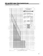
Страница 16: ...14 MD and ND Frame Time Current Curve 600 100A Without Short Time Settings ...
Страница 17: ...MD and ND Frame Time Current Curve 15 1200A Without Short Time Settings ...
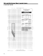
Страница 18: ...16 MD and ND Frame Time Current Curve Ground Fault Trip Data ...
Страница 19: ...MD and ND Frame Time Current Curve 17 Example ...
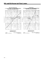
Страница 20: ...18 MD and ND Frame Let Thru Curves ...
Страница 31: ...Installation Diagrams 29 ...
Страница 35: ...I T E Mechanical Interlock M15404 33 Figure 7 ...
Страница 41: ...Installation Diagrams 39 ...
Страница 49: ...Installation Diagrams 47 ...
Страница 50: ...48 I T E Panelboard Connecting Straps 1 ...
Страница 53: ...Installation Diagrams 51 ...


