MD and ND-Frame Universal Test Kit (TS-31)
55
Enter Test to perform
H.
If you press ENTER, you will be prompted for the phase
to test: The TS-31 will display:
Enter phase to test.
Enter one of the following letters:
“A” - Phase A or left pole.
“B” - Phase B or center pole.
“C” - Phase C or right pole.
I.
Press Enter again to start the test. Press any other key to
STOP the test. Once a test has been started, the TS-31
will respond with:
Testing . . .
Be careful at this time. Any key press will abort the test.
Caution:
Handling of the test cable the breaker, or the
trip unit at this time can cause electric shock which
may result in injury and/or death.
J.
The test may take anywhere from a fraction of a second
to minutes to complete, depending on which procedure
was run. If the test passes, the display will show the
following, depending on whether the breaker tripped or
not.
Passed Test xxx xx seconds
Press ENTER to continue.
If the circuit breaker tripped during the test, RESET the
circuit breaker before continuing.
K.
The TS-321 will prompt for the next instructions. The
display will show:
Change: 1 - Test 2 - Catalog 3 - Settings
Enter one of the following numbers:
“1” - Select a new test
“2” - Enter a new catalog number
“3” - Enter new switch settings
If you enter “1” you will be sent to step F Choosing a “2”
will send the program back to step C and entering a “3”
will route program control back to step E. Entering “3”
which sends you back to step E, will be slightly different
the second time through. On the second line after the
prompt for the setting, a number or text in angle brackets
will appear. This will indicate the last setting you entered.
If you DON’T wish to change a setting, just press ENTER.
If you DO wish to change a setting, type in the new setting
and press ENTER.
L.
If you pressed “C” when asked,
Enter test to perform; see instructions,
you will first be prompted by,
Current Transformer Test
Press ENTER to continue or A to abort,
and then by the phase to test. One of the following
messages will then appear depending on the test results:
CT Resistance Test. Phase X Passed
Press ENTER to exit test and continue
CT Resistance Test. Phase X Failed
Press ENTER to exit test and continue
CT Resistance Test. Phase X Open
Press ENTER to exit test and continue
CT Resistance Test. Phase X Short Press ENTER to
exit test and continue
The “Phase X Failed” message indicates that the CT
resistance is neither open nor shorted, but is not within
design tolerance.
M. There are additional ERROR messages which may ap-
pear on the display during this operation which were not
covered previously:
Test Not Running! Check test cable connection.
Press ENTER to continue.
The test set has sensed that current is not flowing
properly in the breaker under test and that there is either
an open or short circuit between the TS-31 and the
breaker trip unit.
Function Not Available
Press ENTER to continue.
You will get this error message if you enter a choice that
is not available, such as entering “G” in step F for ground
fault test on a catalog number that does not have ground
fault.
Inconclusive Test, check settings
Press ENTER to continue or A to abort
NOTE: This warning will appear if you attempt to run a short
time test with the instantaneous pickup set equal to or
below the short time pickup. It would also appear if you
tried to run a long time test with short time pickup set to
2. This is only a warning; the test can still be run. However,
passing or failing the test may not be conclusive
Invalid Input
Press Enter to continue
NOTE: This message will appear if you enter a setting value
that does not exist. For example, a SMD69700NGT has
continuous current settings of 20~ 30, 35, 40, 50, 65, 70,
80, 90, and 100 percent. If you were to enter any other
value that those listed, the above message would ap-
pear.
Test exceeds capability of TS-31
Press ENTER to continue
NOTE: This message is not likely to occur. If it does, it means
that a test requires more current to run than the TS-31
can produce.
Unit too hot, please wait
NOTE: Running many successive high-current long time tests
may over-heat the test set. It will protect itself from
damage by preventing further tests until it has had a
chance to cool down. The display will indicate when
testing can resume.
Содержание I-T-E Sensitrip MD Series
Страница 2: ......
Страница 6: ...4 I T E Sensitrip Digital Circuit Breaker MD and ND Frame Outline Drawings 1 3 Pole ...
Страница 8: ...6 MD and ND Frame Trip Adjustments ...
Страница 12: ...10 MD and ND Frame Time Current Curve 600 1000A With Short Time Delay Set on Fixed Time ...
Страница 13: ...MD and ND Frame Time Current Curve 11 1200A With Short Time Delay Set on Fixed Time ...
Страница 14: ...12 MD and ND Frame Time Current Curve 600 100A With Short Time Delay Set on I2 t ...
Страница 15: ...MD and ND Frame Time Current Curve 13 1200A With Short Time Delay Set on I2 t ...
Страница 16: ...14 MD and ND Frame Time Current Curve 600 100A Without Short Time Settings ...
Страница 17: ...MD and ND Frame Time Current Curve 15 1200A Without Short Time Settings ...
Страница 18: ...16 MD and ND Frame Time Current Curve Ground Fault Trip Data ...
Страница 19: ...MD and ND Frame Time Current Curve 17 Example ...
Страница 20: ...18 MD and ND Frame Let Thru Curves ...
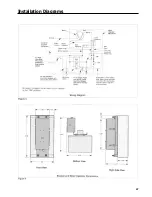
Страница 31: ...Installation Diagrams 29 ...
Страница 35: ...I T E Mechanical Interlock M15404 33 Figure 7 ...
Страница 41: ...Installation Diagrams 39 ...
Страница 49: ...Installation Diagrams 47 ...
Страница 50: ...48 I T E Panelboard Connecting Straps 1 ...
Страница 53: ...Installation Diagrams 51 ...


