


CHAPTER 3 |
DEVICE PROGRAMMING UNIT USER’S MANUAL
TESTING
29
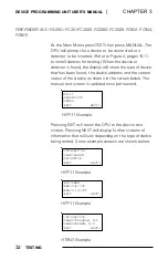
The top line indicates if there are any ground faults
on the loop. The second line indicates how many
devices the DPU has detected on the loop. It may
take more than a minute to detect all of the devices
on the loop. The count will continue to increment as
each additional device or detector is recognized.
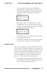
•
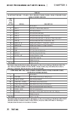
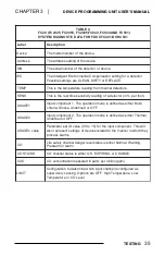
Press SUMMARY to get a summary count of all of
the different devices on the loop. A letter indicates
the type of device (see Table 2 on page 30 for a list
of all available device types). The number to the
right of the letter indicates the quantity of those
devices found on the loop. (For example, P=001
indicates one HFP photo/thermal detector.) Ex-
amples of H-Series (Screen A) and FD-UL Series
(Screen B) displays are shown below:
P=001 T=023 I=020
D=000 R=000 M=000
C=000 Z=010 *=002
<EXIT
NEXT>
Q=002 E=022 W=021
G=000 V=000 N=011
<EXIT
NEXT>
Screen A
Screen B
•
Pressing NEXT shows further summary screens.
Pressing EXIT returns the DPU one screen up to the
top of the loop test display.
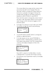
•
Press the DETAIL button to display the type of
device responding at each address. Different letters
represent the device types. (See Table 2 on page
30.) Following is an example of a detail screen
where the numbers indicate the address and the
letters indicate the device types.
000 PP*T D--DD
010 IIIMM MMMMM
NEXT>
<EXIT PREV>
This screen shows the addresses on the loop and
the devices that are responding at each address. The
devices are shown ten to a line, as two groups of
five. The starting address appears on the left-hand


