Chapter 5) 7SR23 DAD Installation Guide
©2013 Siemens Protection Devices Limited
Chapter 5 Page 4 of 24
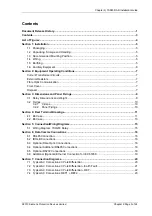
List of Figures
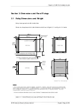
Figure 3.1-1 Overall Dimensions and panel Drilling for Size E6 Epsilon case.......................................8
Figure 3.1-2 Overall Dimensions and panel Drilling for Size E8 Epsilon case.......................................9
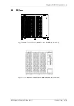
Figure 4.1-1 E6 Standard Comms (USB Front Port, Rear RS485) (See Note 2).................................11
Figure 4.1-2 E6 St Additional Ports (IRIG-B, 2 x F.O. (ST Connectors) ................................11
Figure 4.1-3 E6 St Additional Ports (IRIG-B, RS485) ...........................................................12
Figure 4.1-4 E6 St Additional Ports (IRIG-B, RS232) ...........................................................12
Figure 4.2-1 E8 Standard Comms (USB Front Port, Rear RS485) (See Note 2).................................13
Figure 4.2-2 E8 St Additional Ports (IRIG-B, 2 x F.O. (ST Connectors) ................................13
Figure 4.2-3 E8 St Additional Ports (IRIG-B, RS485) ...........................................................14
Figure 4.2-4 E8 St Additional Ports (IRIG-B, RS232) ...........................................................14
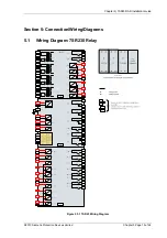
Figure 5.1-1 7SR23 Wiring Diagram..................................................................................................15
Figure 6.1-1 RS485 Data Comms Connections .................................................................................16
Figure 6.3-1 Data Comms to Multiple Devices Using Sigma 1 and F.O. Star Network........................17
Figure 6.3-2 Data Comms to Multiple Devices Using Sigma 3 and F.O. Ring Network .......................17
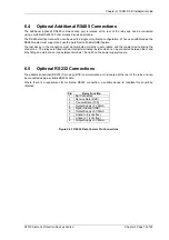
Figure 6.5-1 RS232 Data Comms Pin Connections ...........................................................................18
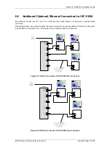
Figure 6.6-1 Ethernet connection for IEC 61850 (star connection) .....................................................19
Figure 6.6-2 Ethernet connection for IEC 61850 (ring connection) .....................................................19
Figure 7.1-1 Connections 3 Pole Differential......................................................................................20
Figure 7.2-1 Connections 3 Pole Differ Earth Fault.................................................................21
Figure 7.3-1 Connections 3 Pole Differ Restricted Earth Fault ................................................22
Figure 7.4-1 Connections Restricted Earth Fault 1 and 2...................................................................23
Содержание 7SR23 DAD
Страница 1: ...Answers for energy 7SR23 DAD High Impedance Protection Relay Reyrolle Protection Devices ...
Страница 2: ......
Страница 4: ...7SR23 DAD Contents 2013 Siemens Protection Devices Limited ...
Страница 40: ...Chapter 1 7SR23 DAD Description Of Operation 2013 Siemens Protection Devices Limited Chapter 1 Page 36 of 36 ...
Страница 60: ...Chapter 3 7SR23 DAD Performance Specification 2013 Siemens Protection Devices Limited ...
Страница 78: ...Chapter 3 7SR23 DAD Performance Specification 2013 Siemens Protection Devices Limited Chapter 3 Page 20 of 20 ...
Страница 80: ...Chapter 4 7SR23 DAD Data Communications 2013 Siemens Protection Devices Limited Chapter 4 Page 2 of 54 ...
Страница 134: ...Chapter 5 7SR23 DAD Installation Guide 2013 Siemens Protection Devices Limited Chapter 5 Page 2 of 24 ...
Страница 156: ...Chapter 5 7SR23 DAD Installation Guide 2013 Siemens Protection Devices Limited Chapter 5 Page 24 of 24 ...
Страница 158: ...Chapter 6 7SR23 DAD Commissioning Maintenance Guide 2013 Siemens Protection Devices Limited Chapter 6 Page 2 of 26 ...
Страница 182: ...Chapter 6 7SR23 DAD Commissioning Maintenance Guide 2013 Siemens Protection Devices Limited Chapter 6 Page 26 of 26 ...
Страница 184: ...Chapter 7 7SR23 DAD Applications Guide 2013 Siemens Protection Devices Limited Chapter 7 Page 2 of 42 ...
Страница 224: ...Chapter 7 7SR23 DAD Applications Guide 2013 Siemens Protection Devices Limited Chapter 7 Page 42 of 42 ...
Страница 225: ......


