Chapter 7) 7SR23 DAD Applications Guide
©2013 Siemens Protection Devices Limited
Chapter 7 Page 4 of 42
List of Figures
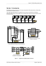
Figure 1-1
Applications of High Impedance Protection......................................................................6
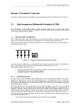
Figure 2-1
Balanced Circulating Current Protection System..............................................................7
Figure 2-2
AC Connections - 3 Phase Differential Protection ..........................................................10
Figure 2-3
AC Connections – Balanced/Restricted Earth Fault Protection.......................................11
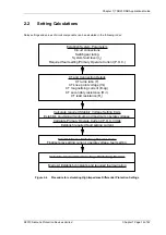
Figure 2-4
Procedure for calculating High Impedance Differential Protection Settings .....................12
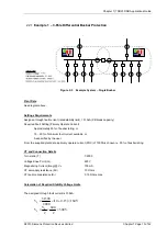
Figure 2-5
Example System – Single Busbar..................................................................................13
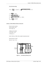
Figure 2-6
3 Pole Differential Relay circuit ......................................................................................15
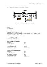
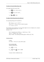
Figure 2-7
Example System – Restricted Earth Fault......................................................................16
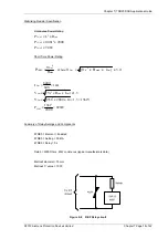
Figure 2-8
REF Relay circuit ..........................................................................................................18
Figure 3-1
CTs Overlapping the CBs..............................................................................................20
Figure 3-2
CTs on Circuit Side of CBs............................................................................................21
Figure 3-3
CTs on Circuit Side of CBs............................................................................................21
Figure 3-4
CTs on ‘Busbar’ Side of CBs .........................................................................................22
Figure 3-5
CTs on ‘Busbar’ Side of CBs .........................................................................................22
Figure 4-1
Logic Diagram: Protection In/Out Switching ...................................................................24
Figure 5-1
Trip Circuit Supervision Scheme 1 (H5) .........................................................................26
Figure 5-2
Trip Circuit Supervision Scheme 2 (H6) .........................................................................27
Figure 5-3
Trip Circuit Supervision Scheme 3 (H7) .........................................................................27
Figure 5-4
Position of Uncleared Faults..........................................................................................28
Figure 5-5
CB Fail Back-Trip from 87/50-2 Element........................................................................29
Figure 5-6
CB Position Monitoring – Double Busbar Arrangement ..................................................29
Figure 6-1
Discrete Relay Circuit Components ...............................................................................30
Figure 6-2
Single Busbar Protection ...............................................................................................31
Figure 6-3
Double Busbar Protection with Check Zone...................................................................32
Figure 6-4
MV Busbar Protection with EF Check ............................................................................33
Figure 6-5
Balanced/Restricted Earth Fault Protection Applied to a Delta/Star
Transformer ..................................................................................................................34
Figure 6-6
Auto-Transformer Protection .........................................................................................35
Figure 6-7
Motor, Reactor or Generator Protection .........................................................................36
Figure 6-8
IEC 61850 Bus ..............................................................................................................37
Figure 6-9
Faults affecting two Protection Zones ............................................................................38
Figure 7-1
Binary Input Configurations Providing Compliance with EATS 48-4 Classes
ESI 1 and ESI 2.............................................................................................................40
Содержание 7SR23 DAD
Страница 1: ...Answers for energy 7SR23 DAD High Impedance Protection Relay Reyrolle Protection Devices ...
Страница 2: ......
Страница 4: ...7SR23 DAD Contents 2013 Siemens Protection Devices Limited ...
Страница 40: ...Chapter 1 7SR23 DAD Description Of Operation 2013 Siemens Protection Devices Limited Chapter 1 Page 36 of 36 ...
Страница 60: ...Chapter 3 7SR23 DAD Performance Specification 2013 Siemens Protection Devices Limited ...
Страница 78: ...Chapter 3 7SR23 DAD Performance Specification 2013 Siemens Protection Devices Limited Chapter 3 Page 20 of 20 ...
Страница 80: ...Chapter 4 7SR23 DAD Data Communications 2013 Siemens Protection Devices Limited Chapter 4 Page 2 of 54 ...
Страница 134: ...Chapter 5 7SR23 DAD Installation Guide 2013 Siemens Protection Devices Limited Chapter 5 Page 2 of 24 ...
Страница 156: ...Chapter 5 7SR23 DAD Installation Guide 2013 Siemens Protection Devices Limited Chapter 5 Page 24 of 24 ...
Страница 158: ...Chapter 6 7SR23 DAD Commissioning Maintenance Guide 2013 Siemens Protection Devices Limited Chapter 6 Page 2 of 26 ...
Страница 182: ...Chapter 6 7SR23 DAD Commissioning Maintenance Guide 2013 Siemens Protection Devices Limited Chapter 6 Page 26 of 26 ...
Страница 184: ...Chapter 7 7SR23 DAD Applications Guide 2013 Siemens Protection Devices Limited Chapter 7 Page 2 of 42 ...
Страница 224: ...Chapter 7 7SR23 DAD Applications Guide 2013 Siemens Protection Devices Limited Chapter 7 Page 42 of 42 ...
Страница 225: ......

