8
05.01
8.5 Start inhibit in the drive modules/safe standstill
8-253
©
Siemens AG 2012 All Rights Reserved
SIMODRIVE 611 Configuration Manual (PJU) – 02/2012 Edition
8.5.2
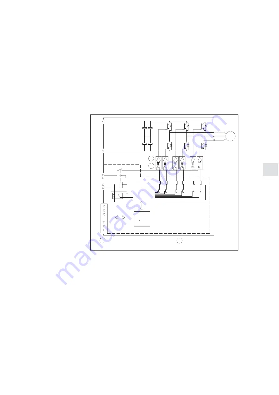
Mode of operation of the start inhibit
The current through the individual motor windings is controlled using the inverter
power module. The motors are fed with sinusoidal current.
A pulse generation logic clocks the six power transistors in a rotating field–ori-
entated pattern. An optocoupler for potential isolation is connected in each tran-
sistor arm between the control logic and the control (gating) amplifier of the
power module.
The start inhibit acts on each specific module. In each of the drive modules, a
positively–driven relay in the inverter control acts in the input circuits of the opto-
couplers.
U2
V2
W2
P5
ASIC
with
gating logic
uP
Closed–loop Control Module
SIMODRIVE 611 universal HRS
M600
P600
M
3~
AS1
AS2
K1 safety relay
663
K1
2
1
2
1 Control amplifier (SIDU–ASIC)
Optocoupler
19
Fig. 8-8
Mode of operation using as an example the SIMODRIVE 611 universal HRS
A relay contact interrupts the power supply of the optocoupler inputs. This
means that the optocoupler blocks and cannot transfer any signal. The pulse
generation logic is inhibited using an additional branch that is electrically iso-
lated.
For the drive modules, these two circuits are controlled from the machine
control through terminal 663 (motor start inhibit). The state of the relay contact in
the pulse power supply circuit is signaled to the external adaptation circuit
through a positively opening contact.
The signaling contact is accessible at the module terminals AS1 and AS2 and
the user can interlock this with his safety–relevant control. When the start inhibit
fails, these start inhibit signaling contacts must disconnect the drive from the
line supply via the power contactor in the line supply infeed (line contactor in the
infeed module).
8 Important Circuit Information
02.03


