Communication System Manual
3WN1, 3WS1 Circuit-Breakers
Version 1.0 (02/98)
Copyright Siemens AG 1998. All rights reserved.
89
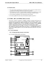
4.4 Special cases
•
The current values transferred by the circuit-breaker which are below the activation limit are
generated in the transformer electronics and must not be evaluated.
•
The trip reasons are stored in the communication processor and are transferred at regular
intervals after a trip. They are not deleted until the circuit-breaker is switched on again.
•
The trip reasons are displayed on the release within a period of 20 ms.
•
The release updates the current values of the transferred phases every 50 ms.
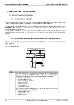
4.5 DP/3WN1, 3WS1 and DP/3WN6 interface modules
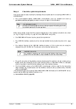
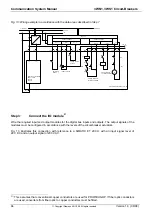
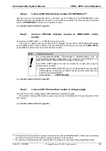
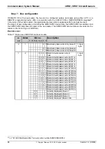
This section contains a description, installation guidelines, operating instructions and
technical data for the interface modules DP/3WN1, 3WS1 (for 3WN1 or 3WS1 circuit-
breakers) and DP/3WN6 (for 3WN6 circuit-breakers). Only the DP/3WN1 interface
modules is illustrated however. All the information also applies to the DP/3WN6
interface module with the exception of the device names and the order numbers.
(Note: the "PROFIBUS-DP" and "3WN6" connectors on the DP/3WN6 interface module
are swapped on products shipped before July 1998, i.e. the PROFIBUS interface is
below and the 3WN6 interface is on top. We shall make special reference to any other
differences.)
4.5.1 Device description
4.5.1.1 Display/operating elements and interfaces
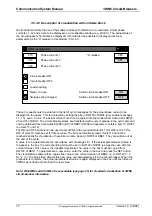
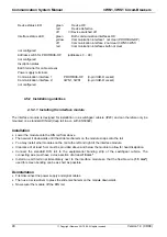
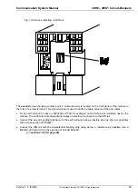
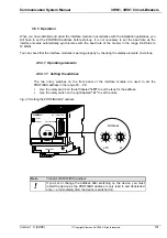
Fig. 14: Display/operating elements and interfaces
Device
Interface
0 1
2
3
4
5
6
7
8
9
Address
3RK1002-0BB00-0AA0
x10
x1
0 1
2
3
4
5
6
7
8
9
24V
0V
3WN1,3WS1
PROFIBUS-DP
DP / 3WN1,3WS1
1 2 3 4 5 6
G/jj.mm.dd
0
1
2
3
5
6
4
7
8
9
10

