Communication System Manual
3WN1, 3WS1 Circuit-Breakers
Version 1.0 (02/98)
Copyright Siemens AG 1998. All rights reserved.
85
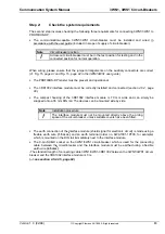
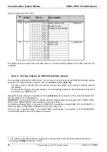
Step 4:
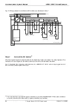
Connect 3RK1002 interface module to PROFIBUS-DP
58
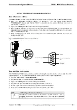
Now you can wire the appropriate 6ES7... connector (up to 12 Mbaud) to the PROFIBUS-DP cable
based on the baud rate required on the bus
59
(cf. connector user guide). Then plug the wired connector
into the "PROFIBUS-DP" socket on the interface module.
(--> see also section 4.5.2.2.3, page 93)
Step 5:
Connect 3RK1002 interface module to 3WN1/3WS1 circuit-
breaker
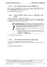
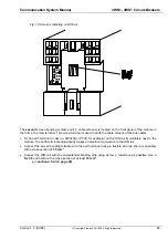
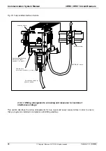
Connection of 3WN1/3WS1 <--> 3RK1002 connecting cable:
ð
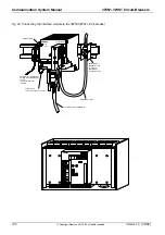
This cable is supplied with the interface and is plugged into the 3WN1, 3WS1/3RK1002 adapter
(9-pin SUB-D socket), which is fitted on the circuit-breaker at the factory, and into the "3WN1, 3WS1"
(9-pin SUB-D) socket on the front of the interface module.
Note
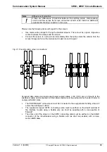
Installation procedure
!
All communication-capable circuit-breakers (fixed-mounted) and all
communication-capable guide frames (for draw-out circuit-breakers) are
fitted with a "3WN1, 3WS1/3RK1002" adapter at the factory.
This 3WN1, 3WS1 adapter can also be ordered as a spare part using the
following order numbers:
•
Adapter "3WN1/3WS1/3RK1002" (0.4 m) for 3WN1/3WS1 fixed-mounted
circuit-breakers, comprising one SUB-D socket and free cable ends, and
including mounting materials.
Order number:
3WX3145-3JA00
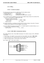
(--> see also section 4.5.2.2.2, page 92)
Step 6:
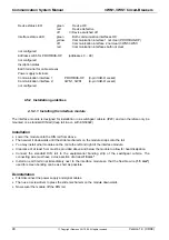
Connect 3RK1002 interface module to voltage supply
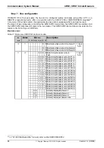
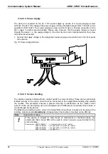
Connect the 24 V DC voltage supply (DIN 19240) to the interface module:
ð
The interface module is fitted with a 4-pole screw terminal to facilitate the through connection of the
24 V supply.
(--> see also section 4.5.2.2.4, page 94)
58)
This assumes that conventional copper conductors are used for PROFIBUS-DP. If fiber optic conductors
are used, converters from fiber optic to copper conductors must be fitted.
59)
The maximum possible baud rate corresponds to the maximum baud rate of the slowest field device.

