
Communication System Manual
3WN1, 3WS1 Circuit-Breakers
106
Copyright Siemens AG 1998. All rights reserved.
Version 1.0 (08/98)
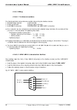
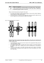
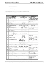
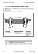
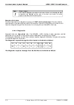
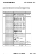
4.5.5 Connecting cables between interface modules and 3WN1/3WS1
The pin assignments of the TTY interface on the 3WN1/3WS1 circuit-breakers have been designed such
that a 9-pole 1:1 connecting cable can be used.
The 3WN1/3WS1 circuit-breakers use the TTY interface in only one direction, i.e. the circuit-breakers can
only transmit, not receive.
Fig. 24: Connecting cable between interface module and circuit-breaker
1
2
3
4
5
6
7
8
9
1
2
3
4
5
6
7
8
9
Driver [ - ]
GND
20mA-Driv.
20mA-Rec.
Receiver [ + ]
Receiv. [ - ]
Driver [ + ]
Driver [ - ]
Receiv.[ + ]
Driver [ + ]
Receiv.[ - ]
3WN1, 3WS1
(passive)
Interface module
(active /
Cable screen (passive)
TTY-Interface
Standard-connecting cable
TTY-Interface
- 9-pin SUB-D socket
- 9-pin SUB-D socket
- Circuit Breaker can only
send data, i.e. the lines
"Receiver (+)" and
"Receiver (-)" are not
configured !
- 2 x 9-pin SUB-D plugs
- Screen 9-pole cable
- Core cross section>= 0,14 mm²
passive)
Note
TTY interface of circuit-breaker
!
The 3WN1/3WS1 circuit-breakers are fitted with a unidirectional interface. The
circuit-breakers can only send data, they cannot receive.
For this reason, the "Receiver (+)" and "Receiver (-)" lines, which are required for
receiving data, are not configured in the TTY interface of the circuit-breakers.


