Communication System Manual
3WN1, 3WS1 Circuit-Breakers
88
Copyright Siemens AG 1998. All rights reserved.
Version 1.0 (08/98)
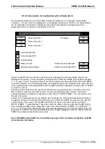
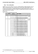
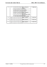
Table 12: Data area of ET 200 U
I/O
Octet
Bit no.
Description
area
7 6 5 4 3 2 1 0
9
1
0 0 1 Switch position ON
1 input byte
0 1 0 Ready to close
1 0 0 Storage spring charged
0 0 0
0 0 0
0 0 0
0 0 0
0 0 0
10
2
0 1 Switch ON
1 output byte
1 0 Switch OFF
0 0
0 0
0 0
0 0
0 0
0 0
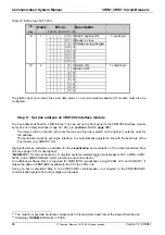
The digital input and output lines and data areas of a communication-capable I/O module must also be
configured.
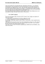
Step 8: Set bus address on 3RK1002 interface module
The bus address defined for 3WN in Step 7 can be set on the front panel of the 3RK1002 interface module
by means of 2 rotary switches (range 00 - 99). (--> section 4.5.3.1.1, page 101)
ð
The rotary switch on the left (x10) sets the tens and the rotary switch on the right (x1) sets the units for
the address.
ð
The baud rate cannot be set on the interface. It is automatically adjusted in line with the baud rate of the
bus master (e.g. SIMATIC S5).
61
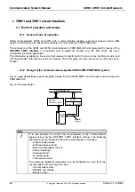
High-performance software is available for the visualization and evaluation of the data transferred from
3VF (see page 35 ff. for description):
"SICAM LCC" for the visualization of complete systems implementing circuit-breakers 3VF, 3WN6, 3WN1,
3WS1, and a SIMOCODE-DP motor protection and control device.
62
An additional software block is required for 3WN1/WS1 visualization using SICAM LCC and SIMATIC. It
makes the data on PROFIBUS available to the PC via an FDL link.
Once you have completed Step 8, the 3WN1/3WS1 circuit-breaker is connected to the PROFIBUS-DP
communication system. No further steps are required.
61
The maximum possible baud rate corresponds to the maximum baud rate of the slowest field device.
62
Shipping of SICAM LCC starts in 10/98.

