13 / 18
Siemens
Room temperature controller radio set REV24RF../SET
CE1N2206en
Building Technologies
2018-11-07
e)
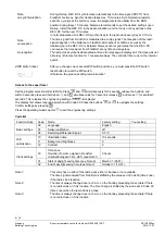
RCR10/868: LED_1 also indicates the radio link quality:
Red
= Insufficient or no radio link
Orange = Good
Green =
Very good
f)
If radio link quality is insufficient, shorten the distance between the REV24RF.. and
RCR10/868.
Repeat the test until quality is sufficient.
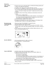
a) Switch off power.
b) Mark the place where the RCR10/868 is located.
c) Loosen the wiring as needed.
d) Mount the receiver at the marked location, wire completely and close the housing.
e) Switch on power.
f) The receiver does not require operation after commissioning.
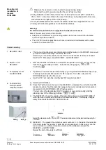
Press the override button
on the receiver to manually override the relay. LED_1
flashes. Override is active for at least 15 minutes. Press again
to remove manual
override.
If the room controller sends a control telegram within these 15 minutes, the telegram is
suppressed and executed only after these 15 minutes. This function allows for testing the
unit connected to the receiver.
After expiration of manual override, the RCR10/868 immediately executes every control
telegram received.
In the even of errors (e.g. empty batteries), the room controller no longer sends control
telegrams. Press the override button
on the receiver to permanently turn on the
connected unit. This function allows you to e.g. run the heating system even if the room
controller is off.
When the room controller resumes operation (e.g. after inserting new batteries), its
control telegrams overwrite manual override. Synchronization takes max. 130 minutes.
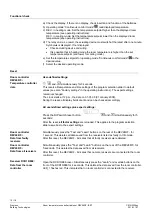
The receiver delivered with REV24RF../SET is connected to the controller at the factory.
Manually connect RCR10/868 and REV24RF.. :
a)
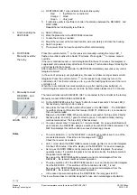
On the RCR10/868 press the “Learn“ button for about 4 seconds: The blue LED_2
flashes slowly, learning mode is active.
b)
Also press the "Learn" button within 20 minutes on the REV24RF.. : The REV24RF..
now either shows confirmation that receiver (RCR 01, RCR02, etc.) is connected or
that connection failed.
Display on the RCR10/868: When connection is successful, the blue LED_2 briefly
flashes quickly, and LED_1 goes from red to green. If connection failed, learning
mode remains active: The blue LED_2 flashes slowly.
c)
You can connect max. 15 receivers to 1 room controller. For unique identification of
each receiver, the REV24RF.. assigns a number to each RCR10/868 connected. The
REV then displays this number after a successful learning process.
·
The error indication
on the REV24RF.. can point out a radio issue to one of the
connected receivers. Check the error message with
.
Check the receiver as needed.
·
LED_1 is red when the RCR10/868 receives a weak, garbled or no control telegram
for about. 65 minutes. Check the display on the REV24RF.. for an error message.
·
As long as the RCR10/868 correctly receives the control telegrams, the receiver
operates normal. If a control telegram is not received correctly, the relay remains in
the position last switched.
As soon as the RCR10/868 again receives a correct control telegram from the
REV24RF.., the receiver resumes normal operation.
·
The relay switches off, if the RCR10/868 receives no or an incorrect control telegram
from the REV24RF… This switches off the controlled unit. LED_1 is red.
As soon as the RCR10/868 again receives a correct control telegram from the
REV24RF.., the receiver resumes normal operation.
·
In the case of power interruption at the RCR10/868, the relay goes to OFF.
This is a software class A controller designed for use at a normal degree of pollution.
5. Finish mounting the
RCR10/868
6. RCR10/868
Manually override
the relay
7. Manually connect
REV24RF.. and
RCR10/868
LED_1 LED_2
LEARN
Notes

