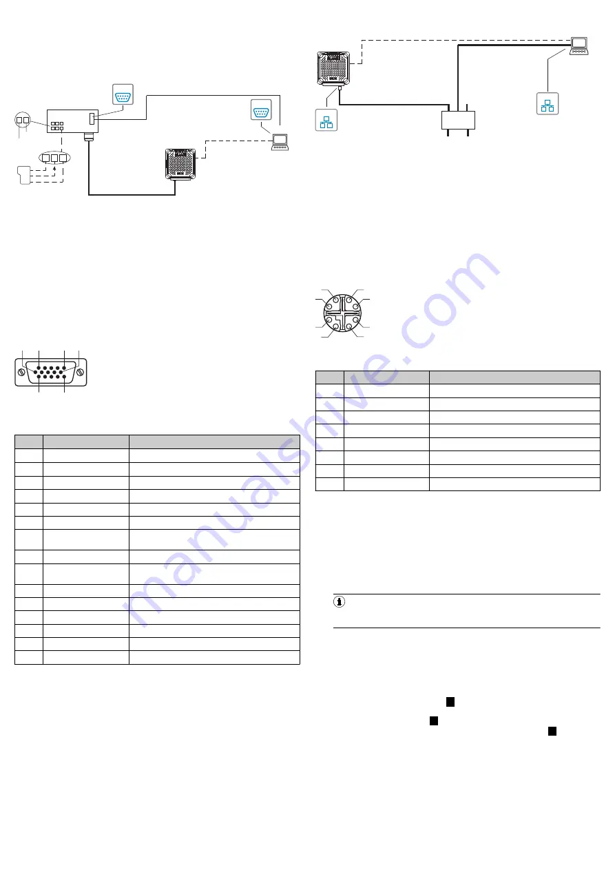
Procedure:
1.
Connect the communication interface (e.g. Ethernet) of the device directly to
the computer (PC) using the suitable cable.
2.
Attach the “Power/Serial Data/CAN/I/0” connection (male connector, M12,
17-pin, A-coded) to the corresponding female connector on the connection
module using a suitable cable.
RFU620-104xx (serial variant)
Configuration
Reading result
display
Transponder
access
Reading
diagnostics
Connection
module
Serial
Serial
SOPAS ET
SOPAS ET
"Power/Serial Data/Aux/CAN/I/O"
(Aux 1, Host 1)
...
...
1 2
V
S
GND
PC
RFU62x-
104xx
"Serial RS-232" (Aux 1)
Cable
4
7
11 10 12
Trigger
sensor
SGND
Sens 1
V
S
1
Out
GND
V
S
Serial
Serial
2
3
Cable
6
"USB" (Aux 2),
for temporary use only
5
Figure 8: Commissioning: Electrical connection block diagram of the
RFU620-104 xx with optional connection module
1
Trigger sensor for read cycle
2
Supply voltage V
S
3
CDB620 or CDM420 connection module
4
Null modem cable (female connector, D-Sub, 9-pin/female connector,
D-Sub, 9-pin), crossed TxD and RxD
5
USB, alternative to Serial RS-232. The USB interface is only for tempo‐
rary use as a service interface.
6
USB adapter cable (male connector, USB, Micro-B type/male connec‐
tor, USB, type A)
7
Configuration with SOPAS ET, prepared representation of the read
result, transponder access or reading diagnostics
“Power/Serial data/CAN/I/O” connection
6
1
10
5
11
15
Figure 9: Male connector, D-Sub-HD, 15-pin
Pin assignment of the “Power/Serial data/CAN/I/O” connection (D-Sub-HD)
Pin
Signal
Function
1
V
S
Supply voltage
2
RxD (RS-232), Aux
Aux interface (receiver)
3
TxD (RS-232), Aux
Aux interface (sender)
4
Sensor 2
Digital input 2
5
GND
Ground
6
RD+ (RS-422/485), Host
Host interface (r)
7
RD– (RS-422/485), Host
RxD (RS-232), Host
Host interface (receiver–)
8
TD+ (RS-422/485), Host
Host interface ()
9
TD– (RS-422/485), Host
TxD (RS-232), Host
Host interface (sender-)
10
CAN H
CAN bus (IN/OUT)
11
CAN L
CAN bus (IN/OUT)
12
Result 1
Digital output 1
13
Result 2
Digital output 2
14
Sensor 1
Digital input 1
15
SensGND
Digital input ground
Procedure:
1.
Connect the 15-pin D-Sub-HD male connector of the connecting cable to the
corresponding female connector on the connection module.
2.
Connect the serial Aux interface (RS-232) of the device to the computer (PC).
To do so, attach the internal “Aux” connection (male connector, D-Sub, 9-pin)
of the connection module to the computer (male connector, D-Sub, 9-pin)
using a null mode cable (e.g. part no. 2014054, 2 m). If the computer does
not have an RS-232 interface, you can also use the USB interface of the
device.
Use of an optional extension cable (e.g. part no. 2043413, 2 m)
To maintain the IP65 enclosure rating for the connecting cable of the device, use
the optional rubber seal, part no. 4038847, between the male and female con‐
nectors of the 15-pin D-Sub-HD male connector, and screw the pin connectors
together.
RFU620-105 xx (PoE version)
Configuration
Reading result
display
Transponder
access
Reading
diagnostics
SOPAS ET
SOPAS ET
PC
"Ethernet (AUX 1)"
Ethernet
Ethernet
Ethernet
Ethernet
PoE Switch
(Endspan)
...
DC 48 V/57 V
PSE
**)
PD
*)
RFU62x-
105xx
*) PD = Powered Devices
6
**) PSE = Power Sourcing Equipment
5
"Ethernet"
Cable
1
4
"Ethernet (Aux 1/Host 1)/Power"
Cable
2
"USB" (Aux 2),
for temporary use only
3
Figure 10: Commissioning: Electrical connection block diagram of the
RFU620-105 xx
1
Adapter cable (male connector, M12, 8-pin, X-coded / male connector,
RJ-45, 8-pin)
2
Adapter cable (male connector, USB, Micro-B type/male connector,
USB, type A)
3
USB, alternative to Ethernet Aux port. The USB interface is only for
temporary use as a service interface.
4
Configuration using SOPAS ET, processed read result display,
transponder access, or reading diagnostics
5
PSE = Energy source
6
PD = Energy consumer
“PoE” connection
1
7
2
6
5
4
3
8
Figure 11: Female connector, M12, 8-pin, X-coded
Pin assignment of the “PoE” connection
Pin
Signal
Function
1
TD+
2
TD–
Sender–
3
RD+
R
4
RD–
Receiver–
5
PoE–
Supply voltage-
6
PoE–
Supply voltage-
7
PoE+
Supply
8
PoE+
Supply
Procedure:
b
Connect the “PoE” connection to the PoE switch using a suitable cable (e.g.
part no. 6049728, 2 m).
General information for all variants
1.
RFU620-101xx and RFU620-104xx
: If necessary, connect a trigger for read
cycles, e.g. a photoelectric sensor to the digital input of the connection mod‐
ule, “Sens 1” (CDB620), “SENS/IN1” (CDB650-204) or “Sensor 1”
(CDM420), see the “Electrical installation” chapter, operating instructions of
the RFID read/write device RFU62x (UHF).
2.
Supply the device with voltage.
NOTE
The voltage supply via a power supply unit must be capable of buffering
a brief power failure of 20 ms.
°
RFU620-101 xx: DC 10 V … 30 V
When using –25 °C to –40 °C: DC 20 V … 30 V
°
RFU620-104 xx: DC 10 V … 30 V
°
RFU620-105 xx: DC 48 V/57 V in accordance with PoE technology.
✓
After successful initialization, the “Device Ready” LED lights up green.
3.
Turn on the PC and start Windows.
Block diagram of all interfaces of the RFU620-101xx (Ethernet variant) together
with the optional connection module:
Block diagram of all interfaces of the RFU620-104xx (serial variant) together with
the optional connection module:
Block diagram of all interfaces of the RFU620-105xx (PoE variant):
6
Commissioning and configuration with computer (Windows
PC)
Adaptation of the device parameters to the application as well as diagnostics in
the event of malfunctions take place as default with the SOPAS ET configuration
software.
8015928/10XW/2019-12-12/en
RFU62x | SICK
5


