6.1 Installing and starting the configuration software
1.
Download and install the latest version of the SOPAS ET configuration soft‐
ware, as well as the current device description files (
*.sdd
):
. In this case, select the “Complete” option as sug‐
gested by the installation wizard. Administrator rights may be required on the
computer (PC) to install the software.
2.
Start the “SOPAS ET” program option after completing the installation. Path:
Start > Programs > SICK > SOPAS ET Engineering Tool > SOPAS.
3.
Establish communication between SOPAS ET and device with the automati‐
cally launching wizard. To do so, select the RFU620 under the devices avail‐
able depending on the connected communication interface, e.g. in the Ether‐
net (default Ethernet address: IP address: 192.168.0.1, subnet mask:
255.255.255.0). SOPAS ET establishes communication with the device and
loads the associated device description file. The
Quickstart
tab opens.
6.2 Detecting a transponder in Quickstart mode
1.
Bring one or more standards-compliant UHF transponders into the working
range of the integrated antenna of the device. The UII/EPC of the individual
transponders must be differentiated so that the device can detect several
transponders.
2.
Click the
Start
button on the
Quickstart
tab of SOPAS ET. SOPAS ET generates
an automated read cycle and lists the detected transponders one after
another in the Quickstart window.
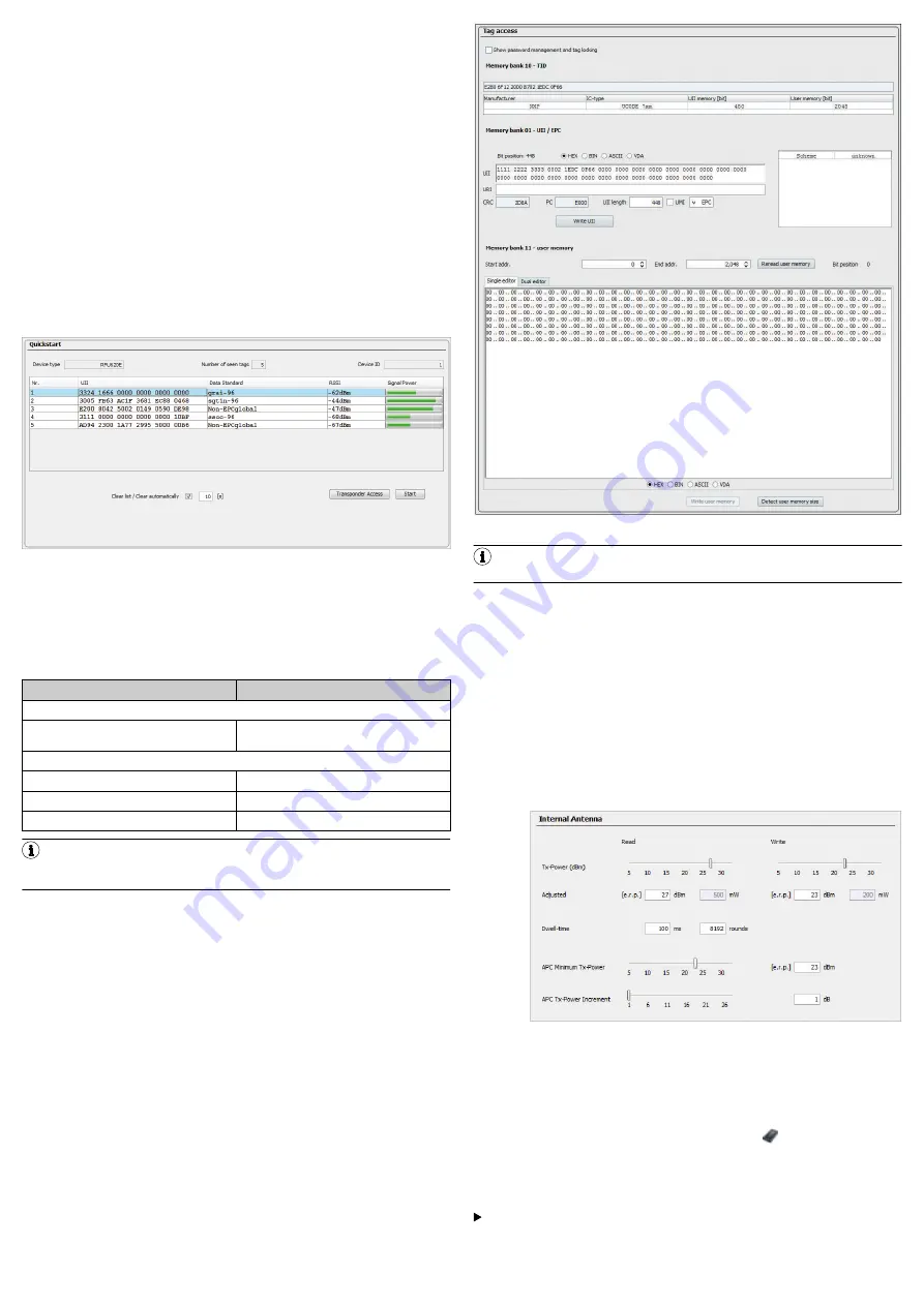
Figure 12: SOPAS ET display of the detected transponders in the
Quickstart
win‐
dow
Feedback about transponder detection in the UHF field
In Quickstart mode, the default lighting behavior of the process feedback LEDs
indicates whether a UHF field is present and whether the device has detected
transponders. The process feedback LEDs are located in the four corners of the
antenna cover and light up blue in this case.
Process feedback LEDs
LED status
Status
At half brightness:
Lit up (permanently)
UHF field available, no transponder in the
field
At full brightness:
Flashing slowly (f = 1.25 Hz)
1 transponder in field
Flashing quickly (f = 2.5 Hz)
2 transponders in field
Flashing faster (f = 5 Hz)
More than 2 transponders in field
NOTE
Quickstart mode is not intended to be used during normal operation. For
operational use, set a read cycle using the object trigger control in SOPAS ET.
6.3 Accessing the data on a transponder
1.
In order to access the memory area of a transponder, click the
Stop
button in
Quickstart
.
2.
Highlight the desired transponder (click it with the mouse).
3.
Click the
Transponder Access
button. The
Transponder Management Access
tab dis‐
plays the content of the selected transponder.
Figure 13: SOPAS ET:
Transponder Access
display window
NOTE
The device cannot write the TID (tag identifier) of the transponder.
6.4 Continuing the configuration
1.
Under SOPAS ET in the left-hand navigation tree, edit the required tabs for
the application using the additional entries under
Parameters
.
These include amongst others:
°
antenna configuration, performance optimization, data pre-processing,
transponder processing
°
Object trigger control (e.g. via digital input “Sensor 1”), data processing
and output
°
Data output interface(s), function of the digital inputs and outputs and
use of an optional memory card if necessary.
2.
Set the transmitting power for the integrated antenna using sliders on the
Antenna Configuration
tab.
°
Regional permissible values for the antenna,
.
°
RFU620 transmitting power default: 15 dBm (30 mW)
Figure 14: SOPAS ET: Example setting for the integrated antenna
3.
Test and, if necessary, modify the settings made during operational use of
the system.
6.5 Completing the configuration
b
Permanently save the entire configuration once it has been successfully
tested:
°
Parameter set in the device: Click the button
.
°
Configuration file on the PC: Click buttons
Device
>
Export SDV file
.
7
Maintenance and care
The device does not contain components that require maintenance.
If it is contaminated (e.g. metal dust), clean the front of the device (antenna
hood) carefully using a soft, damp cloth (with a mild cleaning agent) in order
to achieve the full read and write speed. The antenna hood is made of plas‐
tic.
8015928/10XW/2019-12-12/en
RFU62x | SICK
6


