ADM-880C 07/20/09
49
11.0 FLOWHOOD OPERATING PROCEDURE
The meter handle should be removed from the AirData Multimeter by unscrewing the captive fasteners on the sides. The
meter is inserted into the recess in the FlowHood base, using the captive fastener inside the base to secure it. The two
pneumatic tubes from the flow sensing grid attach to the pneumatic inlets on the meter. The tube from the top side of the
grid connects to the positive (+) pneumatic inlet on the meter; it is important that these connections are not reversed, since
this will cause false flow measurements. The flaps plug inserts into the flaps receptacle on the back of the meter.
The thumbswitch plug connected to the handgrip is inserted into the external read jack on the left side of the meter. The
TemProbe sensor plugs into the temperature input jack on the back of the meter through the cutout designed into the
FlowHood base.
CAUTION: Avoid possible damage by removing all three electrical connections and both pneumatic connections before
removing the meter from the FlowHood base.
Place the FlowHood over the outlet (or inlet) diffuser or grille, so as to capture and direct the air flow through the FlowHood
base. The foam gasket around the edge of the top assembly should be firmly pressed against the ceiling or the edges of the
diffuser. Air flow through the unit should not be blocked or influenced by any object within one foot of the FlowHood base.
The unit should be supported with both hands, one on the handle, and the other at any convenient point on the outside of
the base. Set the flaps control knob to the open position.
Press the READ key or the thumbswitch on the FlowHood handle and the reading will be displayed directly in cfm or liters/sec.
A negative number indicates that the air flow is being exhausted through a return outlet. A second reading with the flaps
closed will be necessary to determine the actual air flow.
SAFETY NOTICE
When using the FlowHood to test air flow at ceiling outlets, be sure that you can safely raise and support
the unit during the measurement. This is especially important when working on a ladder.
11.1 AIR FLOW - NONBACKPRESSURE COMPENSATED READINGS
See Section 9.2 BACKPRESSURE COMPENSATION for a general discussion of backpressure and its effect on any capture
hood device before using the FlowHood for nonbackpressure compensated readings. This technique measures air flow
without compensating
for FlowHood induced backpressure. This method may be used for both supply and return outlets.
Attach the meter and all of its connections to the FlowHood, as described previously. Turn the meter on. The display will
read [FLO HOOD], followed by [CF READ]. Set the flaps control knob to the open position. Place the FlowHood over the
outlet (or inlet) diffuser or grille. Wait two or three seconds to allow the air flow to stabilize, and then press the READ key
or the thumbswitch on the FlowHood handle. The meter will display [FLO HOOD], followed by [CF UNCORR], then either
[LOCAL DENS] or [STD DENS] during the measurement period. The reading will be displayed as [CF u nnnn]. Each
subsequent air flow measurement is triggered by pressing the READ key.
The displayed result is a nonbackpressure compensated air flow reading and represents the flow value of the outlet while
the FlowHood is in place. This flow reading will generally be somewhat less than the actual flow, due to the backpressure
effect of the FlowHood.
11.2 AIR FLOW - BACKPRESSURE COMPENSATED READINGS
Air flow through an outlet (or inlet) is reduced to some degree by
any
capture hood device placed over the opening.
Correction curves had traditionally been used to provide an
average
correction factor for the backpressure effects at different
air flows.
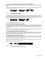
This method measures air flow with compensation for the FlowHood induced backpressure automatically calculated into the
displayed result. Backpressure compensation requires two readings in immediate sequence. The first reading is the flaps
open reading discussed above. The second reading is performed with the flaps closed. The meter automatically determines
the required backpressure compensation calculated from the relationship between the two readings, and displays the
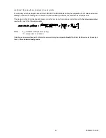
compensated result. A backpressure compensated reading must
always be immediately preceded by a nonbackpressure
compensated (flaps open) reading at the same location
. The meter will register incorrect readings if the uncompensated
reading is taken at another time or any other location.
Any
adjustments or changes to the air flow system between the two
measurements will result in inaccurate results.
This technique may be used for either supply or return outlets. Backpressure compensated readings may be performed at
any flow rate, but are usually unnecessary at flows less than 100 cfm.
Содержание AIRDATA ADM-880C
Страница 42: ...ADM 880C 07 20 09 37 FIGURE 6 3 VELGRID ASSEMBLY...
Страница 50: ...ADM 880C 07 20 09 45 FIGURE 10 1 FRAME STORAGE FIGURE 10 2 FLOWHOOD IN CASE...
Страница 51: ...ADM 880C 07 20 09 46 FIGURE 10 3 FLOWHOOD ASSEMBLY...
Страница 53: ...ADM 880C 07 20 09 48 FIGURE 10 7 1X5 FRAME ASSEMBLY FIGURE 10 8 3X3 FRAME ASSEMBLY...


